Air cushion type tunnel conveyer

A conveyor and air-cushion technology, applied in the field of air-cushion tunnel conveyors and material conveying devices, can solve the problems of limited conveying materials, easy deviation of materials, pollution of the environment, etc., and achieve the effect of small conveying resistance and energy saving.

Inactive Publication Date: 2012-09-12
上海东靖环境工程技术有限公司
View PDF7 Cites 3 Cited by
  • Summary
  • Abstract
  • Description
  • Claims
  • Application Information

AI Technical Summary

Problems solved by technology

This type of belt transmission has the following obvious disadvantages: 1) The material is in an open state, which is easily affected by the external environment such as wind and rain, causing fine materials to fly, polluting the environment, or causing powdery materials to agglomerate, which affects the quality of the material; 2) It is difficult to achieve small bending Radius conveying makes flexible layout difficult, which often leads to high project cost; 3) The material is easy to deviate during the conveying process, especially during heavy-load transportation, resulting in scattered materials; 4) The friction between the belt and the roller is large , high energy consumption and operating costs; 5) fast-wearing parts are damaged quickly, life is short, and maintenance costs are high
However, there are problems such as large turning radius, too long cylindrical area of ​​the conveyor belt, and unbalanced force on the air cushion caused by the inertia of the material during the turning transportation, which is likely to cause friction between the conveyor belt and the air sleeve, and has strict restrictions on the conveyed materials.

Method used


Image

  • Air cushion type tunnel conveyer
  • Air cushion type tunnel conveyer
  • Air cushion type tunnel conveyer

Examples


Embodiment Construction

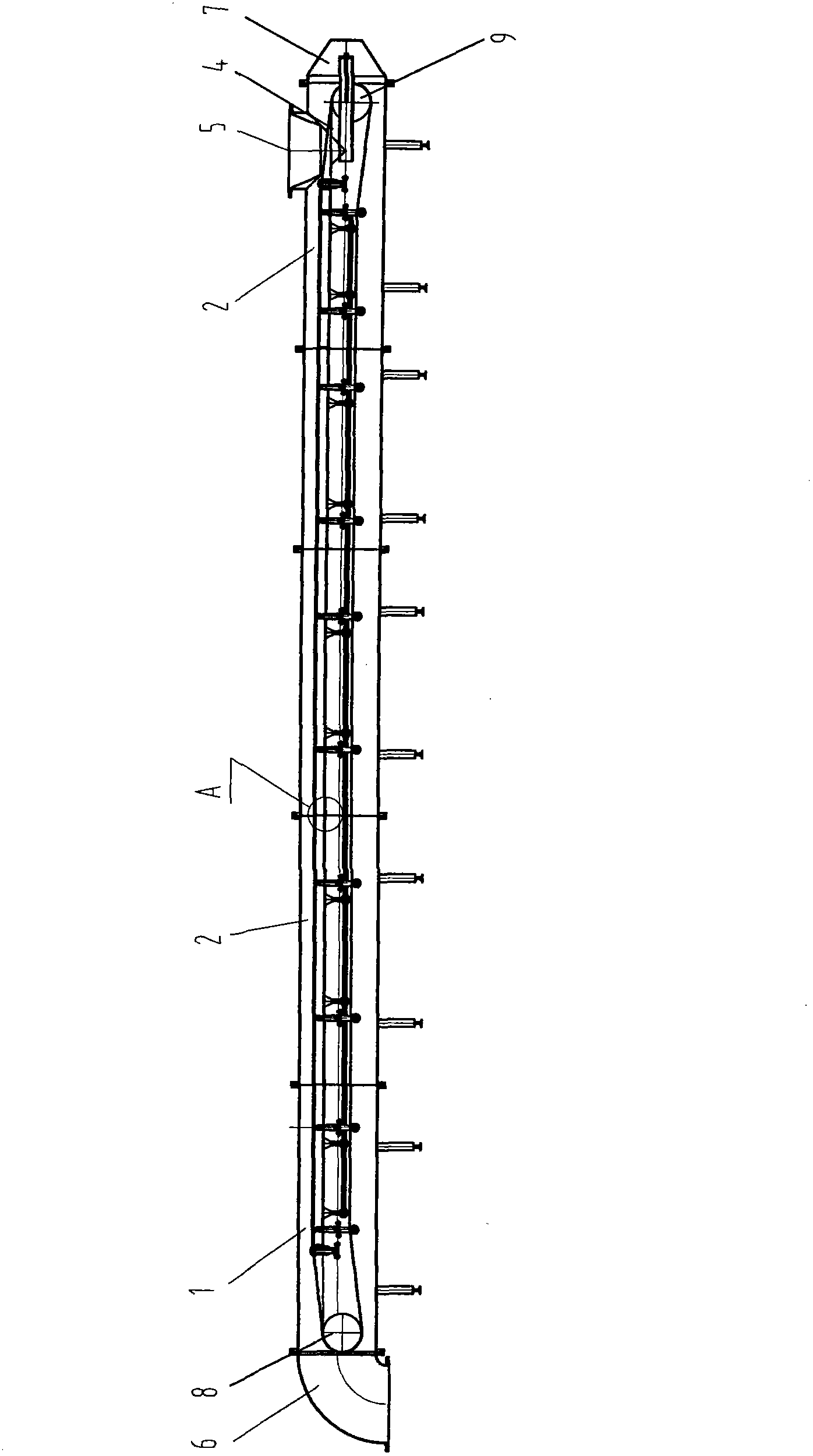
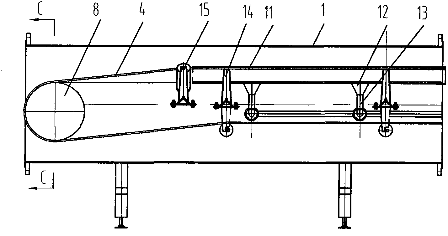
[0019] The basic structure of the air cushion tunnel conveyor in this implementation is as follows: figure 1 As shown, the conveying pipeline with a circular cross section is supported on the column bases distributed at intervals, and is composed of a head section 1 connected to the discharge elbow 6, a number of standard sections 2, and a tail section 3 connected to the tail casing 7. The loop conveyor belt 4 surrounding the built-in driving drum 8 and the reversing drum 9 is installed in the conveying pipeline. The driving drum 8 is connected with the motor speed reducer as the conveying driving device outside the head section. The upper part of the tail section 3 has a funnel-shaped feed opening 5 .

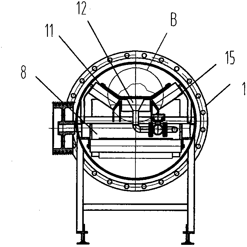
[0020] like Figure 8 As shown, the upper part of the loop conveyor belt 4 is placed on the bracket 11 supported on the conveying pipeline. The cross-section of the bracket is flat-bottomed V-shaped, and the two sides of the notch are respectively formed with hook buckle ed...


PUM


Abstract

The invention relates to an air cushion type tunnel conveyer, and belongs to the technical field of conveying machinery. The conveyer comprises a loop back conveyer belt which is arranged in a conveying pipeline and connected with a conveying driving device in a transmission manner, wherein the upper part of the conveyer belt is arranged on a supporting slot supported by the conveying pipeline; hook-head buckling edges for wrapping the edges of the conveyer belt are respectively arranged on two sides of a notch of the supporting slot; the bottom of the supporting slot is communicated with an air conveying pipeline through an air inlet; and air flow from the air inlet forms an air cushion cavity between the inner surface of the supporting slot and the lower surface of the upper conveyer belt. The air cushion type tunnel conveyer is small in rear conveying resistance; the influence on conveyed materials is avoided, and an air floating pressure difference between the upper surface and the lower surface of the upper conveyer belt can be formed without large air flow; and therefore, energy consumption can be reduced obviously.

Description

technical field [0001] The invention relates to a material conveying device, in particular to an air-cushion tunnel conveyor, which belongs to the technical field of conveying machinery. Background technique [0002] For a long time, belt conveyors have been widely used in the transportation of broken materials such as coal and ore. Its basic structure is that the two ends of the frame are respectively equipped with a drive roller and a reversing roller, a transmission belt is wound between the two rollers, and the upper belt is supported by the load-bearing rollers installed on the frame at intervals. This type of belt transmission has the following obvious disadvantages: 1) The material is in an open state, which is easily affected by the external environment such as wind and rain, causing fine materials to fly, polluting the environment, or causing powdery materials to agglomerate, which affects the quality of the material; 2) It is difficult to achieve small bending Rad...

Claims


Application Information

Patent Timeline
Patent Type & Authority Applications(China)
IPC IPC(8): B65G15/08B65G15/60
Inventor 郁祥兴
Owner 上海东靖环境工程技术有限公司
Why Eureka
Try Eureka