Antiskid ladder
A ladder and anti-skid technology, applied in ladders, buildings, building structures, etc., can solve the problems of wasting manpower, etc., and achieve the effect of convenient operation, light weight and simple production
- Summary
- Abstract
- Description
- Claims
- Application Information
AI Technical Summary
Problems solved by technology
Method used
Image

Examples
Embodiment 1
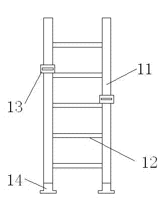
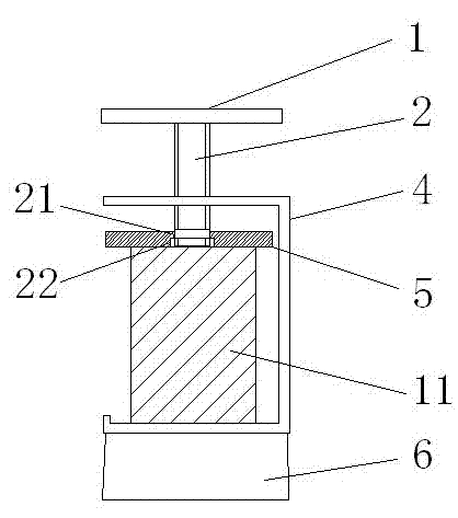
[0023] Non-slip ladders, such as figure 1 Shown, comprise the ladder that is made up of two ladder rods 11 and several root steps 12. Anti-skid device 13 is set on described ladder bar 11, and the installation position of anti-skid device can be determined according to actual situation, can be symmetrically arranged on ladder bar 11, also can be figure 1 In the asymmetric structure, the anti-slip device is mainly used to hook on the surface of a fixed object to keep the ladder stable as a whole. The foot ends of the two ladder rods 11 are provided with anti-skid pads 14 . An embodiment of the anti-skid device 13 of the present invention is figure 1 , figure 2 As shown, the anti-slip device includes a support frame 4, and the support frame 4 is made of a section of channel steel. The channel steel is clamped on the ladder bar 11 from one side, and the waist of the channel steel is positioned at the stepping side of the ladder bar. One wing plate of the channel steel is ag...
Embodiment 2
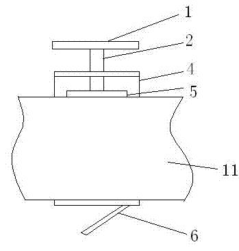
[0025] The difference from Example 1 is that the ladder bar 11 has a circular cross section, a connecting plate 7 is set on the outside of the pressing plate 11, and a clamp clamping the ladder bar is fixedly welded under the connecting plate 7 8. The clamp 8 has an arc-shaped section corresponding to the ladder bar. The hoop 8 can keep the relative stability of the ladder bar of the circular section and the anti-skid device. The centers of the screw rod 2, the pressing plate 11, the connecting plate 7, and the clip 8 are located on the same straight line. A nut 3 is also welded on the upper side of the wing plate that the channel steel cooperates with the screw rod 2 . The screw rod 2 and the pressing plate 5 are in the form of a cooperation between the boss 10 and the groove, such as image 3 As shown, an outwardly protruding boss 10 is provided at the end of the screw rod that cooperates with the pressing plate, and a groove for locking the boss is provided at the corresp...
Embodiment 3
[0027] The difference between this embodiment and Embodiment 1 is that although the lower part of the screw rod 2 and the pressure plate 5 are also threaded, the threaded holes provided on the pressure plate are blind holes, and the depth of the blind holes on the pressure plate is preferably pressed. Half the thickness of the tight plate. The anti-skid device 13 of this structure is different from Embodiment 1 and Embodiment 2 when it is installed on the ladder 11. The pressing plate 5 and the screw rod 2 are operated separately. First, the pressing plate 5 is pressed against the ladder bar. Then the screw rod 2 is slowly screwed into the blind hole on the pressing plate 5 for fixing the pressing plate.
PUM
 Abstract
Description
Claims
Application Information
 - R&D
- Intellectual Property
- Life Sciences
- Materials
- Tech Scout
- Unparalleled Data Quality
- Higher Quality Content
- 60% Fewer Hallucinations
Browse by: Latest US Patents, China's latest patents, Technical Efficacy Thesaurus, Application Domain, Technology Topic, Popular Technical Reports.
© 2025 PatSnap. All rights reserved.Legal|Privacy policy|Modern Slavery Act Transparency Statement|Sitemap|About US| Contact US: help@patsnap.com