
A shunting control method, device and system for an electric locomotive

A shunting and locomotive technology, applied in the field of electric locomotive shunting control, can solve the problems of small effective moving range of the driver controller and difficult operation of the driver

Active Publication Date: 2014-10-22
ZHUZHOU ELECTRIC LOCOMOTIVE CO LTD
View PDF6 Cites 0 Cited by
  • Summary
  • Abstract
  • Description
  • Claims
  • Application Information

AI Technical Summary

Problems solved by technology

[0004] In view of this, the main purpose of the present invention is to provide a method, device and system for shunting control of electric locomotives, which solves the problem in the prior art that the effective movement range of the driver's controller is small during shunting control, resulting in difficult operation for the driver

Method used


Image

  • A shunting control method, device and system for an electric locomotive
  • A shunting control method, device and system for an electric locomotive
  • A shunting control method, device and system for an electric locomotive

Examples


Embodiment Construction

[0094] In order to make the above objects, features and advantages of the present invention more comprehensible, the embodiments of the present invention will be further described in detail below in conjunction with the accompanying drawings and specific implementation methods.

[0095] The method of the present invention is aimed at the problem that in the shunting process of the prior art, the operable range of the traction brake handle of the driver controller is small and the driver's operation is difficult, and the traction force is limited in the shunting mode when the traction working condition value, while maintaining the braking force value during braking conditions.

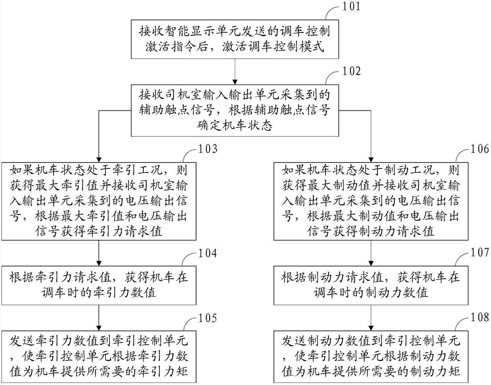
[0096] Based on the above ideas, see figure 1 Shown, method of the present invention comprises the following steps:

[0097] Step 101: After receiving the shunting control activation command sent by the intelligent display unit, activate the shunting control mode;

[0098] Step 102: receiving the auxi...


PUM


Abstract

The invention discloses an electric locomotive shunting control method, which is used for realizing shunting control of an electric locomotive. The method comprises the steps that: a shunting control mode is activated after a shunting control activating command sent by an intelligent display unit is received; an auxiliary contact signal acquired by an input-output unit of a cab is received, and the state of the locomotive is determined according to the auxiliary contact signal; a maximum traction value / a maximum brake value is obtained, a voltage output signal acquired by the input-output unit of the cab is received, and a traction force request value / a braking force request value is obtained according to the maximum traction value / the maximum brake value and the voltage output signal; a traction force value / a braking force value of the locomotive in shunting is obtained according to the traction force request value / the braking force request value; and the traction force value / the braking force value is sent to a traction control unit, so that a needed traction moment / braking moment is provided for the locomotive by the traction control unit according to the traction force value / the braking force value. The invention also discloses an electric locomotive shunting control system and device.

Description

technical field [0001] The invention relates to the railway industry, in particular to a shunting control method, device and system for electric locomotives. Background technique [0002] In the production process of railway transportation, except for the arrival, departure, passage and operation of the train at the station, all purposeful movement of rolling stock is collectively called shunting. In the prior art, the shunting control method is that the locomotive control system calculates the traction force and electric braking force of the locomotive according to the traction / braking curve of the locomotive according to the actual position of the traction brake handle of the driver controller. Because the load of the locomotive is much lower than that in normal operation during the shunting process of the locomotive, the traction power required by the locomotive is very small at this time. Therefore, the driver controller mainly changes in the traction area close to the ...

Claims


Application Information

Patent Timeline
Patent Type & Authority Patents(China)
IPC IPC(8): B61C17/12
Inventor 李顺李希宁王位颜罡胡亮温中建廖洪涛
Owner ZHUZHOU ELECTRIC LOCOMOTIVE CO LTD
Learn More