Al technical title is built by PatSnap Al team. It summarizes the technical point description of the patent document.
A multi-functional micro-tiller technology, applied in the field of micro-tillers, can solve the problems of time-consuming and labor-intensive operation, poor effect, and easy rollover of micro-tillers, etc., and achieve the effect of saving time, effort and light operation
Inactive Publication Date: 2012-08-22
杨正华
View PDF7 Cites 3 Cited by
Summary
Abstract
Description
Claims
Application Information
AI Technical Summary
This helps you quickly interpret patents by identifying the three key elements:
Problems solved by technology
Method used
Benefits of technology
Problems solved by technology
[0003] The existing micro-tillers mainly have the following deficiencies during use: 1. The existing micro-tillers only have two walking wheels when plowing the field, and the operator needs to hold the handrails tightly with both hands to keep the entire micro-tiller in balance Therefore, it takes time and effort for the operator to operate; once the two walking wheels encounter bumps when they miss their hands, the micro tillage machine is easy to roll over; 2. It needs to be operated by a person with a strong body and a certain strength in the hand. It is not suitable for the elderly and women who work and stay in the plowing field, and the operation is not suitable, resulting in a narrow range of suitable people; 3. The existing micro tillage machines generally have defects such as low farming efficiency and poor effect
Method used
Image
Click on the blue label to locate the original text in one second.
Reading with bidirectional positioning of images and text.
Examples
Embodiment Construction
[0029] The present invention will be described in further detail below in conjunction with the accompanying drawings and specific embodiments.
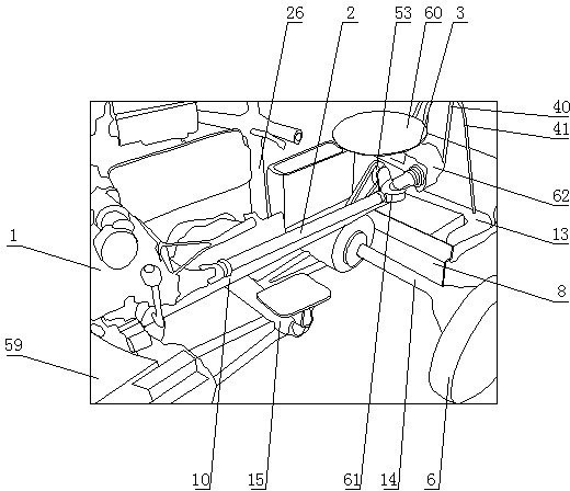
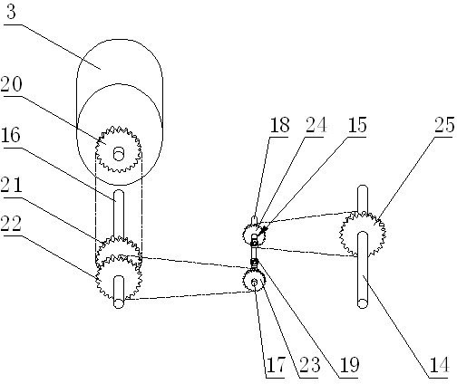
[0030] Such as Figure 1-7As shown, the high-efficiency multifunctional tiller includes engine 1 (gasoline engine is adopted in this embodiment), transmission shaft 2, speed reducer 3, front wheel 4, frame, rotary tiller shaft 5, steering mechanism, rear wheel 6 , wheel driving mechanism, rotary tiller group lifting mechanism, lifting locking mechanism and a vibration-proof mechanism that prevents rotary tiller shaft 5 from vibrating up and down during travel. The engine 1 drives the transmission shaft 2, and the transmission shaft 2 is connected with the worm 63 of the worm gear 62 through the steering universal joint 61, and the worm gear 64 of the worm gear 62 drives the power input shaft 65 of the speed reducer 3. The transmission shaft 2 drives the rotary tiller shaft 5 to rotate through the rotary tiller transmission part. The...
PUM
Abstract
The invention discloses a high-efficiency multifunctional power tiller which comprises an engine, a driving shaft, a reducer, a front wheel, a rack, a rotary blade shaft, a steering mechanism, a rear wheel, a wheel driving mechanism and a rotary blade group lifting mechanism, wherein the engine transfers power to the reducer through the driving shaft, and the driving shaft drives the rotary blade shaft to rotate through a rotary tillage driving component. According to the invention, the bottom of the rack is provided with a front wheel driving shaft, a rear wheel driving shaft and the rotary blade shaft, the rotary blade shaft and the rear wheel driving shaft are separate, the rear wheel is arranged on the rear wheel driving shaft, and four wheels are driven to walk when the power tiller is operated; the rotary blade shaft only drives a rotary blade blade, the whole power tiller keeps balance through four road wheels, a manipulator does not need to use force to maintain the balance of the whole power tiller, the operation is portable, the time is saved, the labour is saved, and old men and women can operate the high-efficiency multifunctional power tiller; and the whole power tiller walking, the whole power tiller turning and the rotary tillage operation can be used for realizing a machinery automatic combination process, the farming efficiency is high, and the farming effect is good.
Description
technical field [0001] The invention relates to an agricultural machine, in particular to a tiller. Background technique [0002] At present, the micro tillage machine that occurs on the market is mainly made up of engine, speed change mechanism, traveling wheel, rotary tiller, guiding device, frame and clutch device. The engine is installed on the frame, and the engine is connected to the speed change mechanism placed under the frame through a belt drive. The output shaft of the speed change mechanism is connected to the road wheel and the rotary tiller. The road wheel and the rotary tiller share the same output shaft. It is determined by the shifting device, the guide device is connected with the frame, the clutch device is installed on the frame, and the clutch device is connected with the transmission mechanism. [0003] The existing micro-tillers mainly have the following deficiencies during use: 1. The existing micro-tillers only have two walking wheels when plowing t...
Claims
Application Information
Patent Timeline
Application Date:The date an application was filed.
Publication Date:The date a patent or application was officially published.
First Publication Date:The earliest publication date of a patent with the same application number.
Issue Date:Publication date of the patent grant document.
PCT Entry Date:The Entry date of PCT National Phase.
Estimated Expiry Date:The statutory expiry date of a patent right according to the Patent Law, and it is the longest term of protection that the patent right can achieve without the termination of the patent right due to other reasons(Term extension factor has been taken into account ).
Invalid Date:Actual expiry date is based on effective date or publication date of legal transaction data of invalid patent.