
Composite left-right-hand transmission line type narrow band wide-range frequency scan antenna

A frequency scanning antenna, compound left and right hand technology, applied in the field of electromagnetism

Inactive Publication Date: 2012-08-15
NAT SPACE SCI CENT CAS
View PDF3 Cites 13 Cited by
  • Summary
  • Abstract
  • Description
  • Claims
  • Application Information

AI Technical Summary

Problems solved by technology

[0012] The purpose of the present invention is to overcome the defect that the existing frequency scanning antenna needs to traverse a very wide frequency band to achieve a certain range of scanning, thereby providing an antenna that can achieve a wide range of scanning angles in a relatively narrow frequency band

Method used


Image

  • Composite left-right-hand transmission line type narrow band wide-range frequency scan antenna
  • Composite left-right-hand transmission line type narrow band wide-range frequency scan antenna
  • Composite left-right-hand transmission line type narrow band wide-range frequency scan antenna

Examples


Embodiment Construction

[0027] Before describing the embodiments of the present invention in detail, the relevant principles will be described first.

[0028] As mentioned in the background art, when the CRLH leaky-wave antenna in the prior art is applied to frequency scanning, it needs to traverse a wide frequency band to achieve a certain range of scanning, which limits the use of the leaky-wave antenna. What the present invention aims to achieve is to realize scanning in a large angle range within a relatively narrow frequency band. It can be seen from the formula (2) in the background technology that in order to realize the scanning of a large angle range in a narrow frequency band, it is necessary to make the propagation constant β(ω) change from -k to 0 to +k 0 The change, ie the propagation constant must be sensitive to changes in frequency. Taking the derivative of formula (2), we have

[0029] dβ / dω = 1 p ...


PUM


Abstract

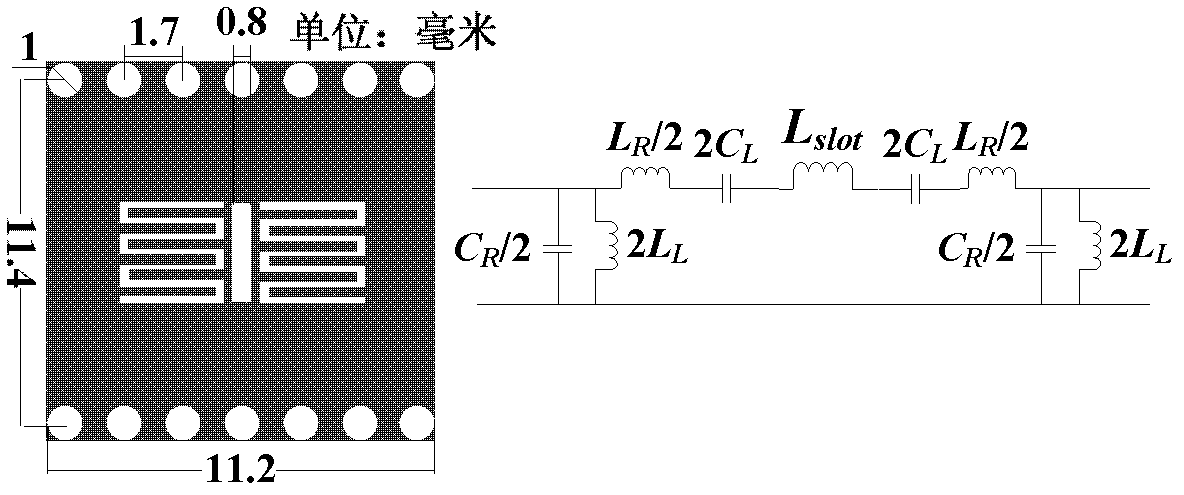
The invention relates to a composite left-right-hand transmission line type narrow band wide-range frequency scan antenna, which comprises a plurality of antenna elements. The plurality of antenna elements are arranged adjacently in sequence, wherein each antenna element comprises a plane baseplate; a row of metal through holes arranged in periods are arranged at each of the upper side and the lower side of the plane baseplate; a gap is arranged at the center of the plane baseplate; and two interdigital capacitors which are of an interdigital shape are respectively distributed at two sides of the gap. With adoption of the composite left-right-hand transmission line type narrow band wide-range frequency scan antenna, scan at wide-angle scope in a narrower band can be realized.

Description

technical field [0001] The invention relates to the field of electromagnetism, in particular to a compound left-handed transmission line type narrow-band wide-range frequency scanning antenna. Background technique [0002] When the electromagnetic wave propagates along the traveling wave structure, if radiation is continuously generated along this structure, the radiated wave is called leaky wave, and the structure that generates leaky wave is called leaky wave antenna. Leaky wave antennas are widely used in the radar field, such as scanning by changing the frequency, so they are also called frequency scanning antennas. In the prior art, there are various types of leaky-wave antennas, such as rectangular waveguide uniform leaky-wave antennas, microstrip leaky-wave antennas, and the like. [0003] With the rapid development of electromagnetic metamaterials (Metamaterials), as a kind of electromagnetic metamaterials, transmission lines based on Composite Right / Left-Handed (CR...

Claims


Application Information

Patent Timeline
Patent Type & Authority Applications(China)
IPC IPC(8): H01Q13/10H01Q1/38H01Q21/00
Inventor 杨青山张云华张祥坤
Owner NAT SPACE SCI CENT CAS
Learn More