
Electric power assisting device for bicycles

A technology of electric power assist and bicycle, which is applied in the direction of wheel transmission, chain/belt transmission, vehicle parts, etc. It can solve the problems of difficult bicycle maintenance and modification, unsatisfactory climbing ability, increased cost and weight, etc. Achieve easy maintenance and modification, reduce cost and weight, and enhance operational stability

Inactive Publication Date: 2012-08-15
SUZHOU IND PARK TONGSHENG BICYCLE
View PDF7 Cites 6 Cited by
  • Summary
  • Abstract
  • Description
  • Claims
  • Application Information

AI Technical Summary

Problems solved by technology

[0003] However, there are the following problems in the use of hub motors as electric drive devices for electric bicycles: 1. Since the hub motors directly drive the wheels to output torque, the speed ratio cannot be changed, That is to say, there is no way to reduce the speed and increase the output torque by shifting gears like a car, so the climbing ability is often not satisfactory; 2. In order to ensure sufficient output torque to make up for the lack of climbing ability, a larger power motor, which will inevitably increase the cost and weight, and will also increase the burden on the battery
3. Since the hub motor and the wheel are connected through spokes, it is difficult for non-professionals to assemble it by themselves, and it is often not easy to repair and modify the bicycle.

Method used


Image

  • Electric power assisting device for bicycles
  • Electric power assisting device for bicycles
  • Electric power assisting device for bicycles

Examples


Embodiment

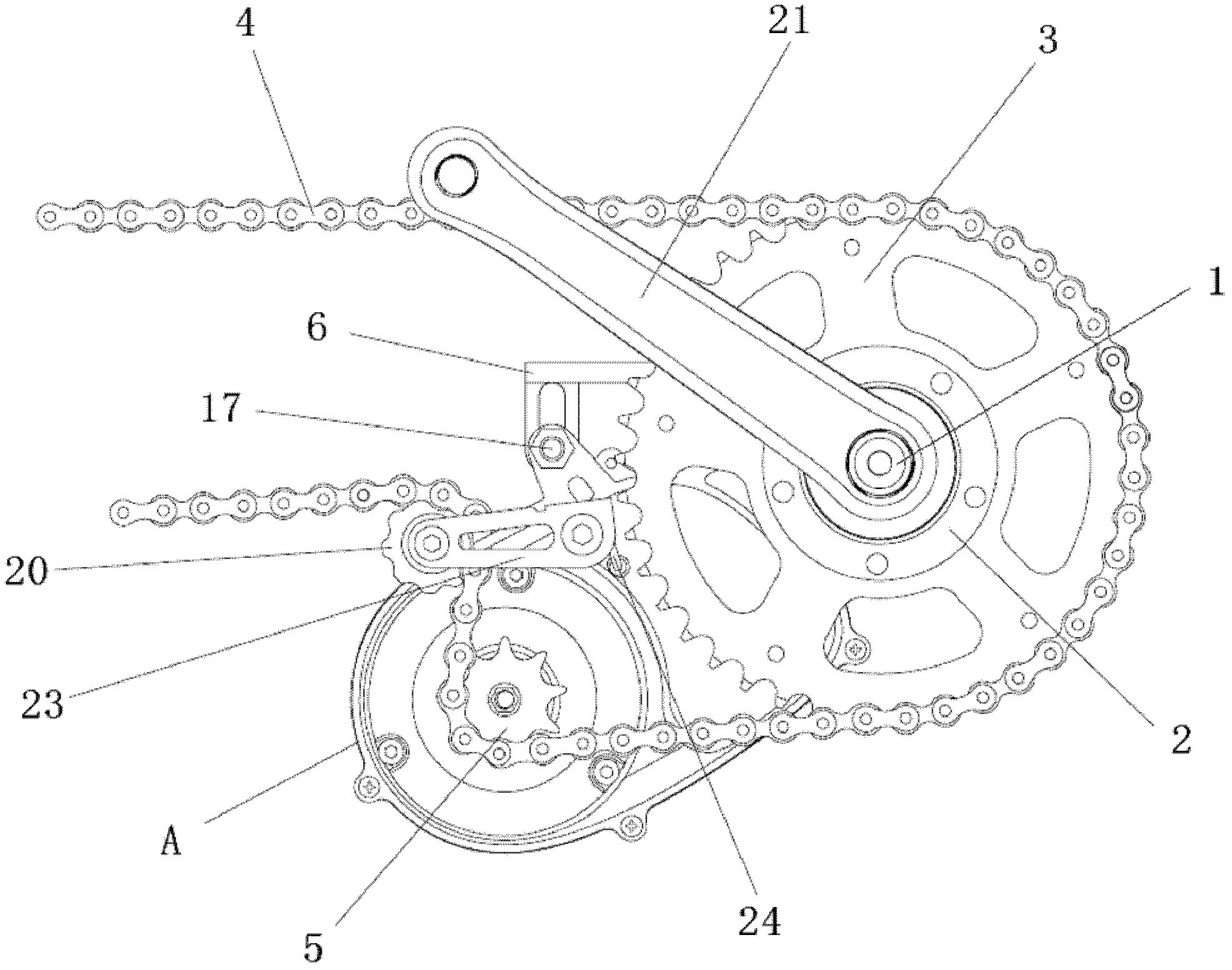
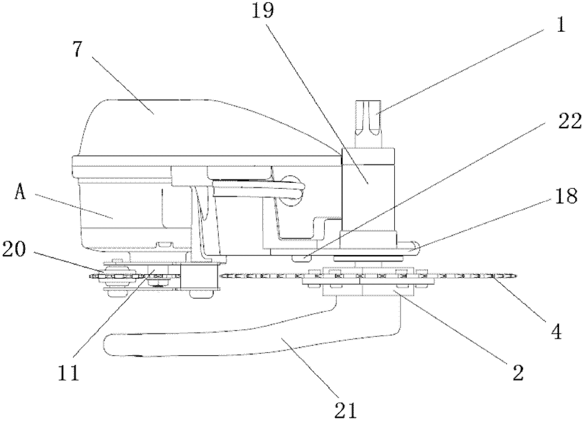
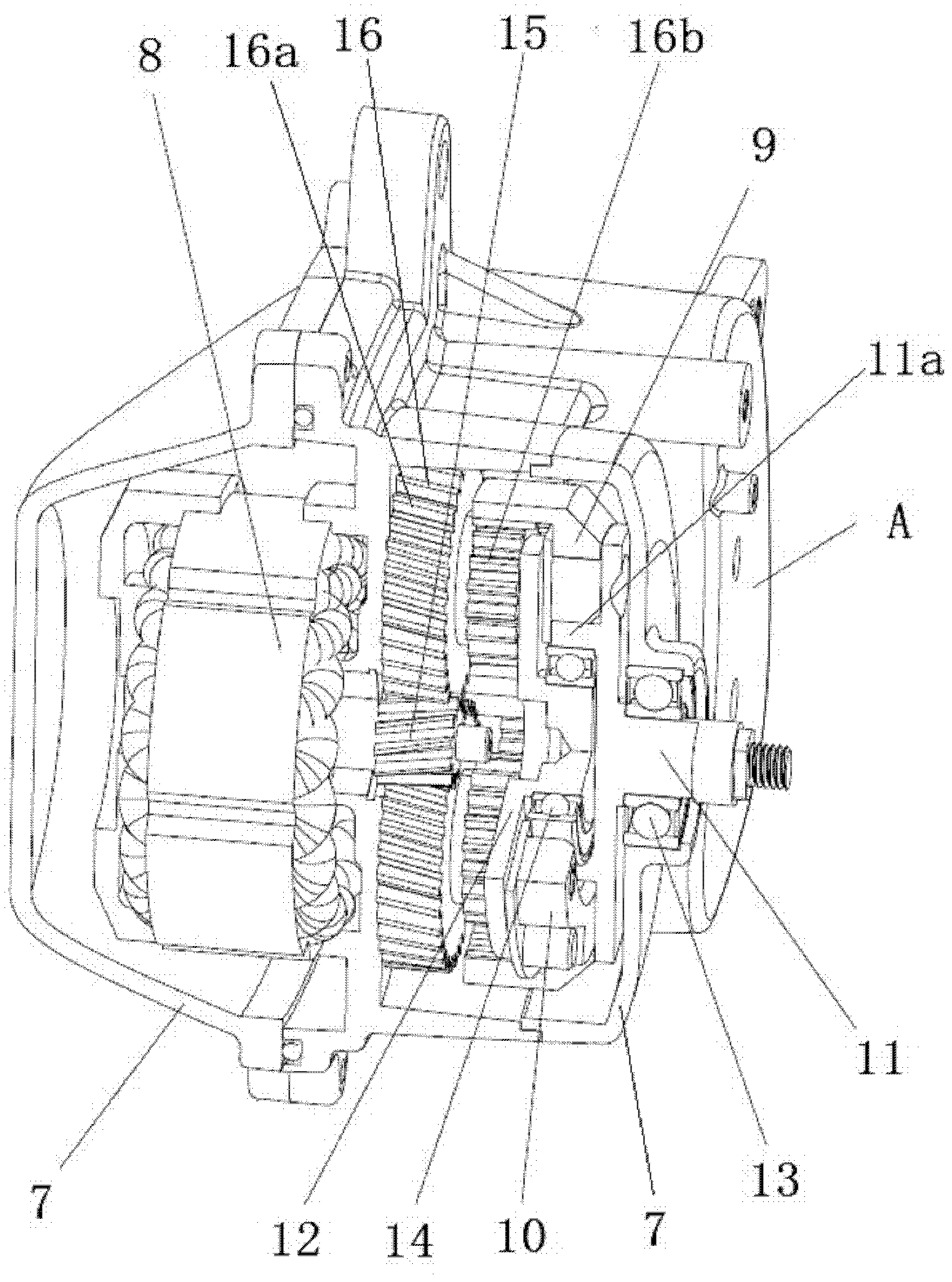
[0026] Example: Combination figure 1 As well as figure 2 and image 3 The bicycle electric assistance device provided by the present invention is mainly provided by the central axis 1, toothless flywheel 2, dental tray 3, chain 4, electric driver charter 5, installation rack 6, electric driver A, connecting board 18, 18.Tensioning chain wheel 20, curved handle 21, tensor 23, and tensor spring 24 are jointly composed.

[0027] Specifically figure 1 It is shown in, like conventional technologies, the bike frame (not drawn in the figure) is fixed with a central axis sleeve 19, which is set in the middle shaft sleeve 19, the two ends of the central axis 1There are crank 21, and the stroke 21 is installed with a pedal (not drawn in the picture).The toothless flywheel 2 is assembled on the central axis 1 by the toothless flywheel one -way clutch (not visible in the picture), and the dental plate 3 is fixed on the toothless flywheel 2.The bicycle rear wheels (not drawn in the picture) are...


PUM


Abstract

The invention discloses an electric power assisting device for bicycles, which is characterized in that the device comprises a middle axle, a gearless flywheel and a chain wheel, wherein the middle axle is arranged on a bicycle frame, the gearless flywheel is assembled on the middle axle by a gearless flywheel overrunning clutch, the chain wheel is fixed on the gearless flywheel, and the chain wheel is connected with a flywheel fixed on a rear bicycle wheel by a chain; the electric power assisting device for bicycles also comprises an electric driver and an electrically driven sprocket; the electric driver comprises a shell, a motor, a planet gear reducing mechanism, an inner gear ring, an inner gear ring overrunning clutch and an output shaft, wherein the shell is fixed on the bicycle frame, and the motor, the planet gear reducing mechanism, the inner gear ring, the inner gear ring overrunning clutch and the output shaft are arranged in the shell; a rotating shaft of the motor is in transmission connection with the inner gear ring by the planet gear reducing mechanism; the inner gear ring is assembled on the output shaft by the inner gear ring overrunning clutch; the output shaft extends out of the shell and is fixed with the electrically driven sprocket; and the electrically driven sprocket is meshed with the chain. The electric power assisting device for bicycles, disclosed by the invention, is simplified in structure, stable in operation and large in output torque, and can greatly enhance the climbing capacity of an electric bicycle.

Description

Technical field [0001] The invention involves a bicycle electric help device. Background technique [0002] Due to its light -saving and pollution -free characteristics, electric bicycles are increasingly promoted in my country.Most of the current electric drives used on conventional electric bicycles are wheel motors. This hub motor is usually used by the hub shell installed on the main axis through the bearing.The hub with a fixed hub is composed of the hub.The gear deceleration mechanism is mainly composed of the solar gear fixed on the motor rotor and the planetary gear meshing with the solar gear.Drive rotation.The clutch is assembled on the axis with the planetary gear.During the specific work: the battery and controller are used to drive the motor rotation, and the motor rotor rotates the planetary gear and gear of the tooth through the solar gear, and the torque is driven by the gear to drive the hub shell through the coupling one -way clutch.The wheel hub shell is bound ...

Claims


Application Information

Patent Timeline
Patent Type & Authority Applications(China)
IPC IPC(8): B62M6/60B62M11/14B62M9/16
CPCB62M6/70
Inventor 马庆一
Owner SUZHOU IND PARK TONGSHENG BICYCLE
Learn More