
Sliding pressure curve correcting method and device

A sliding pressure curve and back pressure technology, which is applied to engine components, engine starting, machine/engine, etc., can solve problems such as reducing economy, losing accuracy, and complex changes

Active Publication Date: 2015-01-21
ELECTRIC POWER RES INST OF STATE GRID ZHEJIANG ELECTRIC POWER COMAPNY +1
View PDF2 Cites 1 Cited by
  • Summary
  • Abstract
  • Description
  • Claims
  • Application Information

AI Technical Summary

Problems solved by technology

[0004] However, the sliding pressure curve provided by the manufacturer is calculated and drawn step by step according to the theory of variable working conditions, which has high accuracy in theory, but in actual operation, local operating parameters (mainly back pressure, i.e. steam turbine Exhaust pressure) complex changes, the curve loses its accuracy, for example, affected by seasonal changes, the back pressure is changing all the time, the temperature difference of circulating cooling water in summer and winter is 30 ℃, and the back pressure difference is as high as 6KPa , for a 600MW steam turbine, the affected output is about 35MW. Therefore, if the sliding pressure curve is still operated, the economical efficiency of unit operation will be reduced. Therefore, the sliding pressure curve needs to be corrected to adjust the unit’s Optimize the sliding pressure operation to improve the economy of unit operation

Method used


Image

  • Sliding pressure curve correcting method and device
  • Sliding pressure curve correcting method and device
  • Sliding pressure curve correcting method and device

Examples


Embodiment Construction

[0032] In order to enable those skilled in the art to better understand the scheme of the present application. The following will clearly and completely describe the technical solutions in the embodiments of the application with reference to the drawings in the embodiments of the application. Apparently, the described embodiments are only some of the embodiments of the application, not all of them. Based on the embodiments in this application, all other embodiments obtained by persons of ordinary skill in the art without creative efforts shall fall within the scope of protection of this application.

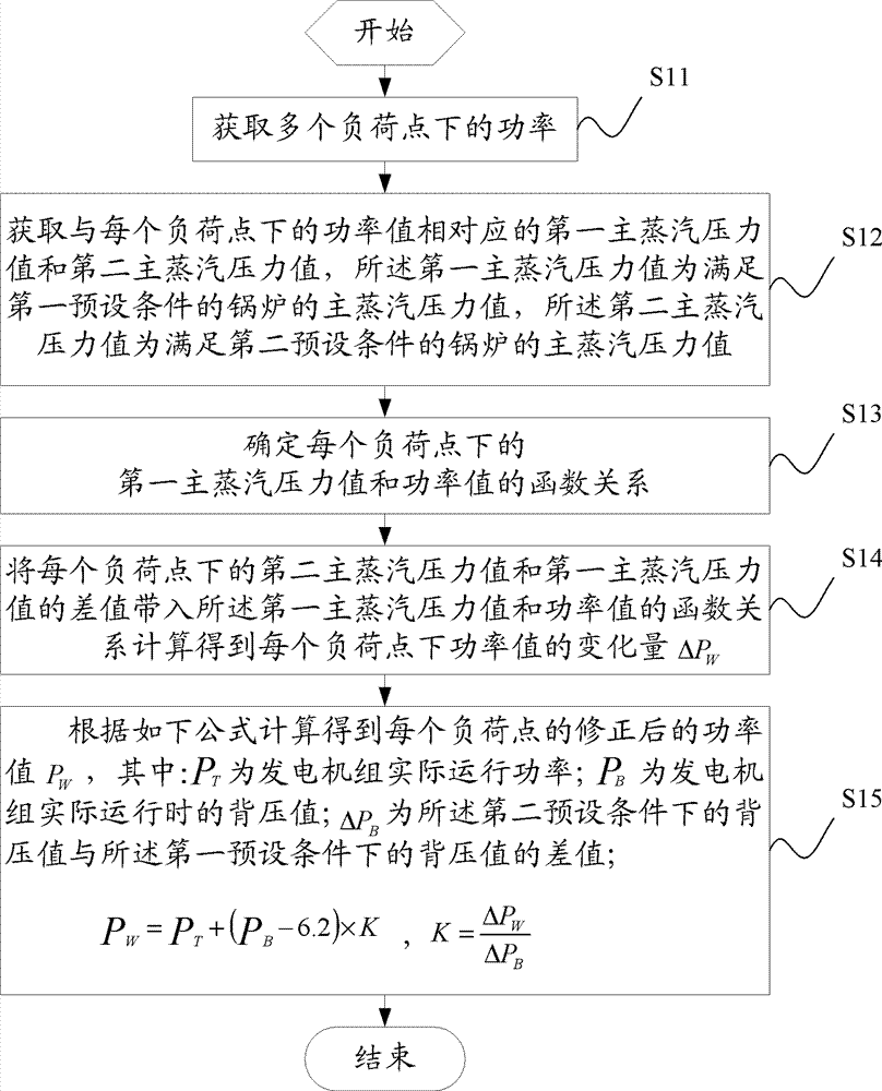
[0033] The flow chart of a sliding pressure curve correction method provided by the embodiment of the present application is as follows: figure 1 shown, including:

[0034] Step S11: Obtain power values ​​at multiple load points;

[0035] Determine multiple load points, and obtain multiple power values ​​in sequence, each power value corresponds to a load point.

[0036]Step S...


PUM


Abstract

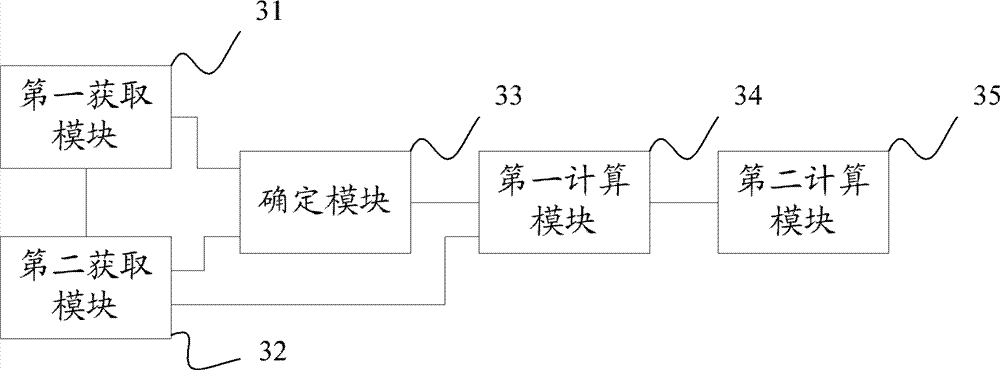
The invention discloses a sliding pressure curve correcting method, which comprises the following steps that: the power values at a plurality of load points are obtained, in addition, a first main steam pressure value and a second main steam pressure value corresponding to the power values at each load point are obtained, the difference value of the first main steam pressure value and the second main steam pressure value at each load point is introduced into the function relation of the power value and the first main steam pressure value at the load point, the variable quantity delta PW of the power value at each load point is obtained through calculation, the back pressure item correcting factor K is obtained through calculation according to the delta PW and the back pressure change quantity delta PB, and the power value after the correction is obtained according to a formula of PW=PT+(PB-6.2)*K, so the sliding pressure operation mode of a machine unit at each load point is carried out according to the function relationship of the power value and the first main steam pressure value at the load point. The method has the advantages that the sliding pressure optimization curve is obtained through the practical operation of the machine unit, the back pressure item correction on the load in the sliding pressure curve is carried out in the practical operation, and the precision of the sliding pressure curve is improved. The invention also provides a sliding pressure curve correcting device.

Description

technical field [0001] The present application relates to the technical field of power control, in particular to a sliding pressure curve correction method and device. Background technique [0002] Sliding pressure operation is an operation mode of steam turbine generator set. During sliding pressure operation, the opening of the high-pressure valve of the steam turbine remains unchanged under different loads, and the output power of the unit depends on changing the pre-machine pressure (also called the main steam pressure, its size is maintained by the boiler) to achieve. [0003] In order to ensure the economical operation of the unit, when the steam turbine is put into production, the manufacturer will provide a sliding pressure curve, which determines the variable load operation mode of the unit. The sliding pressure curve is used to change the main steam pressure so that the power of the unit reaches the target load value. [0004] However, the sliding pressure curve ...

Claims


Application Information

Patent Timeline
Patent Type & Authority Patents(China)
IPC IPC(8): F01D19/00
Inventor 罗志浩陈卫张彩尹峰童小忠
Owner ELECTRIC POWER RES INST OF STATE GRID ZHEJIANG ELECTRIC POWER COMAPNY
Learn More