Magnetic coil assembly

A technology of magnetic coils and components, applied in the direction of coils, electrical components, electromagnetic relays, etc., can solve the problems of winding coils and wire disconnection at the same time

Inactive Publication Date: 2012-08-01
LSIS CO LTD
View PDF5 Cites 4 Cited by
  • Summary
  • Abstract
  • Description
  • Claims
  • Application Information

AI Technical Summary

Problems solved by technology

As a result, when the winding time is reduced by increasing the rotation speed of the motor, there may be a problem that the wire is disconnected while winding the coil

Method used


Image

  • Magnetic coil assembly
  • Magnetic coil assembly
  • Magnetic coil assembly

Examples


Embodiment Construction

[0034] From the following description of preferred embodiments of the present disclosure with reference to the accompanying drawings, objects of the present disclosure, configurations for achieving the above objects, and working effects thereof will be clearly understood.

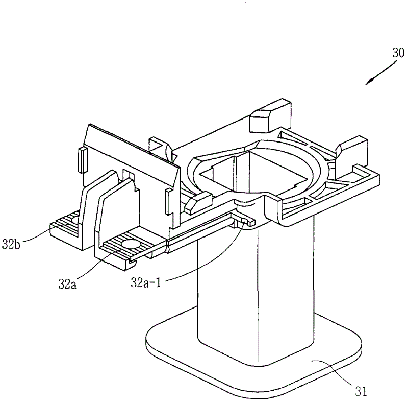
[0035] refer to Figure 5 to Figure 7 , the magnetic coil assembly 30-1 according to the preferred embodiment of the present disclosure includes a bobbin 31, a magnetic coil 33, a pair of terminals 32a, 32b, a first coil fixing protrusion 32a-1, a second coil fixing protrusion 31a, and the third coil fixing protrusion 32b-1.

[0036] The bobbin 31 is made of an electrically insulating material such as synthetic resin, and may typically include a square columnar body portion having an inner hollow and flange portions formed on both end portions in the length direction of the body portion. The upper flange portion of the flange portion includes: a pair of extensions extending longitudinally in one direction ...


PUM


Abstract

The present disclosure provides a magnetic coil assembly for suppressing the generation of broken wire in a coil as well as reducing a winding time, the magnetic coil assembly according to the present disclosure comprise a bobbin; a magnetic coil wound around the bobbin; a pair of terminals fixedly installed at the bobbin; a first coil fixing protrusion portion extended from the terminal to fix a starting end portion of a first coil half which is a half of the entire length of the magnetic coil; a second coil fixing protrusion portion extended from the bobbin to fix a starting end portion of a second coil half which is the remaining half of the magnetic coil, and fix an terminals end portion of the first coil half; and a third coil fixing protrusion portion extended from the terminal to fix a terminal end portion of the second coil half.

Description

technical field [0001] The present disclosure relates to magnetic contactors, and more particularly, to magnetic coil assemblies for magnetic contactors. Background technique [0002] refer to figure 1 , generally, the exposed portion of the magnetic contactor 100 can be roughly divided into an upper frame 10 and a lower frame 20 . [0003] Refer to as internally configured figure 2 , figure 1 A typical magnetic contactor 100 may include a fixed core 1, a movable core 4, a coil 33, a bobbin 31, a cross bar 8, a movable contact 6, a fixed contact 7, and a return spring 9, and the above-mentioned components are housed on the frame 10 and lower frame 20. [0004] The fixed core 1 may be fixed and disposed at the inner bottom surface of the lower frame 20 and configured in a divided 'E'-shaped core. The bobbin 31 may be inserted into the central portion of the 'E'-shaped fixed core 1 , and the coil 33 may be wound around the bobbin 31 . Therefore, when the current flows i...

Claims


Application Information

Patent Timeline
IPC IPC(8): H01H50/44
CPCH01H2050/446H01F5/04H01H50/546H01H50/16H01H50/44
Inventor 宋基凤
Owner LSIS CO LTD
Why Eureka
Try Eureka