Movable type power system of renewable energy

A technology of renewable energy and power system, applied in the field of renewable power energy system and mobile renewable energy power system, which can solve problems such as low energy utilization rate

Inactive Publication Date: 2012-08-01
王德恒
View PDF0 Cites 1 Cited by
  • Summary
  • Abstract
  • Description
  • Claims
  • Application Information

AI Technical Summary

Problems solved by technology

Power oversupply forces utilities to rely on more polluting and less efficient energy sources to meet peak demand, rather tha

Method used


Image

  • Movable type power system of renewable energy
  • Movable type power system of renewable energy
  • Movable type power system of renewable energy

Examples


Embodiment Construction

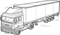
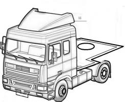
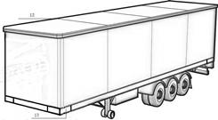
[0028] figure 1 , figure 2 , image 3It is a three-dimensional view of a mobile renewable power system mobile vehicle. The mobile container vehicle unit 10 includes a container truck traction head 11, a container body 12 and a hydraulic support system 13. The container traction head 11 is a high-power traction For automobiles, the container body 12 is a rectangular container installed on the chassis, and the hydraulic support system 13 is respectively installed at the front and rear ends of the container body 12. The hydraulic support system 13 is scalable. When the mobile container unit 10 moves , the hydraulic support system 13 shrinks to the inside of the container vehicle body 12, and when the mobile container unit 10 is working, the hydraulic support system 13 extends outside the container vehicle body 12 to support the work of the entire system.

[0029] Figure 4 It is a structural diagram of the vertical axis wind power generator unit 30, which is composed of a ver...


PUM


Abstract

The invention aims at providing a movable type power system of renewable energy, which is characterized by comprising a movable container vehicle unit, a perpendicular shaft wind power generator unit, a solar Sterling generator unit, a high-power energy storage unit, a pluggable battery collecting box unit and a power output/input unit. The perpendicular shaft wind power generator unit, the solar Sterling generator unit, the high-power energy storage unit, the pluggable battery collecting box unit and the power output/input unit are installed on the movable container vehicle unit. When the movable type power system of the renewable energy is moved, systems of the perpendicular shaft wind power generator unit and the solar Sterling generator unit are folded and dismantled to be installed on a fixing position of the movable container vehicle unit, and side doors of a container vehicle of the movable container vehicle unit are folded and are in a movable state. When the movable type power system of the renewable energy is operated, the side doors of the container vehicle of the movable container vehicle unit are put down and unfolded, and all systems of the perpendicular shaft wind power generator unit and the solar Sterling generator unit are installed in place, extend, and are in operating state.

Description

technical field [0001] The invention relates to a renewable electric energy system, in particular to a mobile renewable energy electric system, which belongs to the field of distributed electric energy. Background technique [0002] When the world is plagued by energy shortages, through the promotion and application of distributed energy systems, not only energy efficiency has been greatly improved, but energy independence has also been achieved. The distributed energy system refers to the small-scale, small-capacity, and modularized energy system. Because it can improve energy utilization and power supply security, realize on-demand energy supply and provide users with more choices, the distributed energy system has become a global power system. An important development direction of the industry and the energy industry. [0003] The energy utilization rate of distributed energy systems is much higher than that of centralized power supply systems in most countries that rely...

Claims


Application Information

Patent Timeline
IPC IPC(8): B60P3/00F03D9/00F03D3/00F03G6/00
CPCY02E10/46Y02E10/74
Inventor 王德恒
Owner 王德恒
Why Eureka
Try Eureka