
Image processing apparatus, image processing system and image processing method

An image processing device and image processing technology, applied in image communication, electrical digital data processing, special data processing applications, etc., can solve problems such as increasing data size, hindering the efficiency of tabular operation, and meaningless tabulation

Inactive Publication Date: 2012-07-25
MURATA MASCH LTD
View PDF1 Cites 17 Cited by
  • Summary
  • Abstract
  • Description
  • Claims
  • Application Information

AI Technical Summary

Problems solved by technology

In the former case, there is a problem that the size of the tabulated data increases unnecessarily and also hinders the improvement of the operational efficiency of the tabulation.
On the other hand, in the latter case, the resulting user has to revisit the original document, so tabulating does not make sense

Method used


Image

  • Image processing apparatus, image processing system and image processing method
  • Image processing apparatus, image processing system and image processing method
  • Image processing apparatus, image processing system and image processing method

Examples


no. 1 approach

[0043]

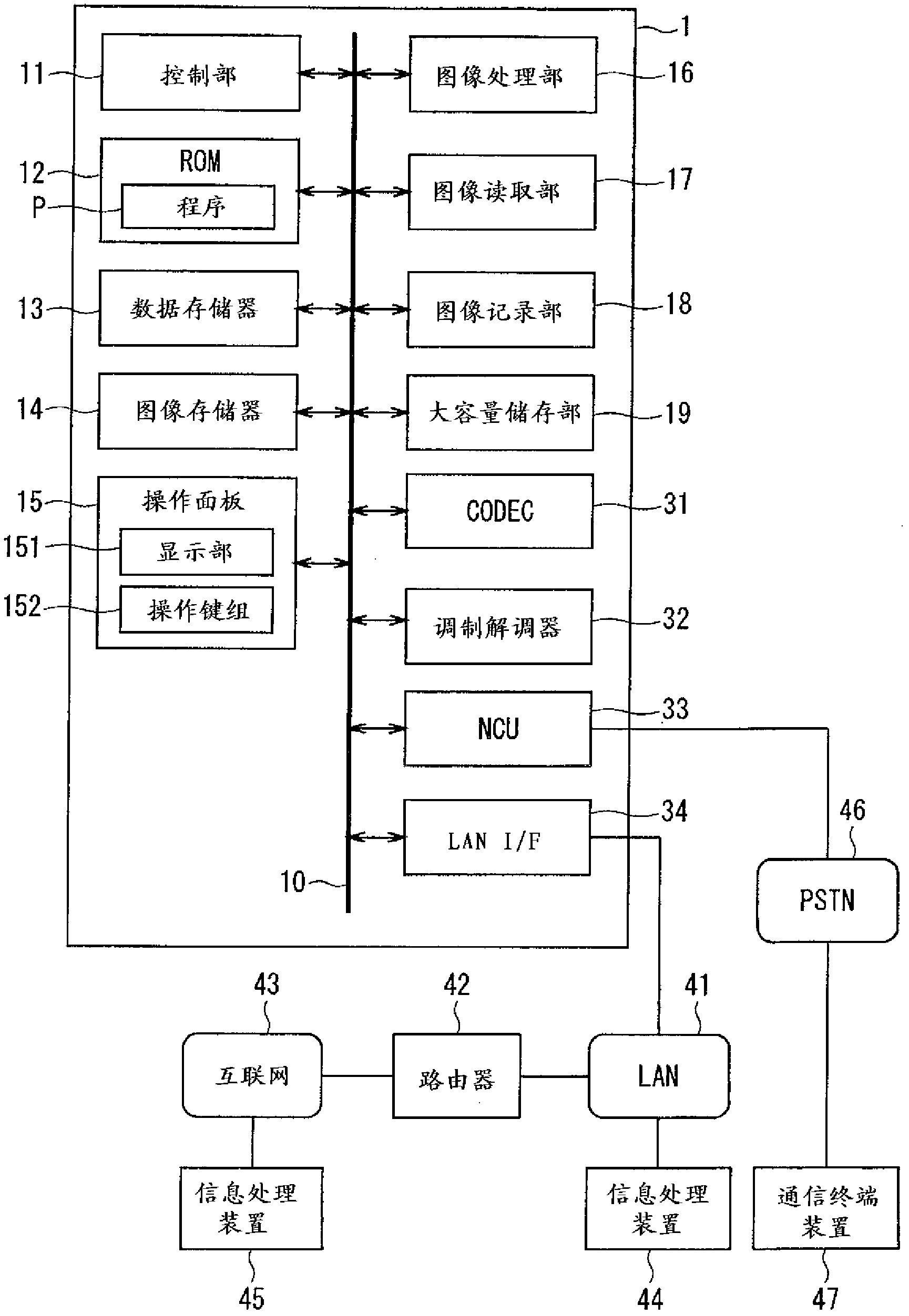
[0044] figure 1 It is a diagram showing the configuration of the digital multi-function peripheral 1 according to the embodiment of the present invention. The digital multifunction peripheral 1 is configured as a multifunction peripheral (MFP device) having multiple functions such as a FAX function, a copy function, a scan function, and a print function.

[0045] The digital multi-function peripheral 1 is a process that combines a control unit 11, a ROM 12, a data memory 13, an image memory 14, an operation panel 15, an image processing unit 16, an image reading unit 17, an image recording unit 18, a large-capacity storage unit 19, and a communication relationship. The sections 31 to 34 are electrically connected via the bus 10 .

[0046] The control unit 11 is constituted by a CPU. The control unit 11 controls each of the aforementioned hardware units based on the program P stored in the ROM 12 to realize the functions of the digital multi-function peripheral 1 ....

no. 2 approach

[0132]

[0133] refer to Figure 15 An image processing system 100 according to a second embodiment of the present invention will be described. Figure 15 It is a block diagram showing the functional configuration of the image processing system 100 .

[0134] The image processing system 100 includes the digital multifunction peripheral 1 according to the first embodiment, and one or more information processing devices connected to the digital multifunction peripheral 1 via a communication line. For example, there are a digital multi-function peripheral 1 and an information processing device (for example, a personal computer) 44 connected thereto via a LAN 41 . In addition, the configuration of the image processing system 100 is not limited thereto, and, for example, may be configured to further include an information processing device 45 (or, instead, an information processing device 44) connected to the digital multifunction peripheral 1 via the Internet 43 (refer to figu...


PUM


Abstract

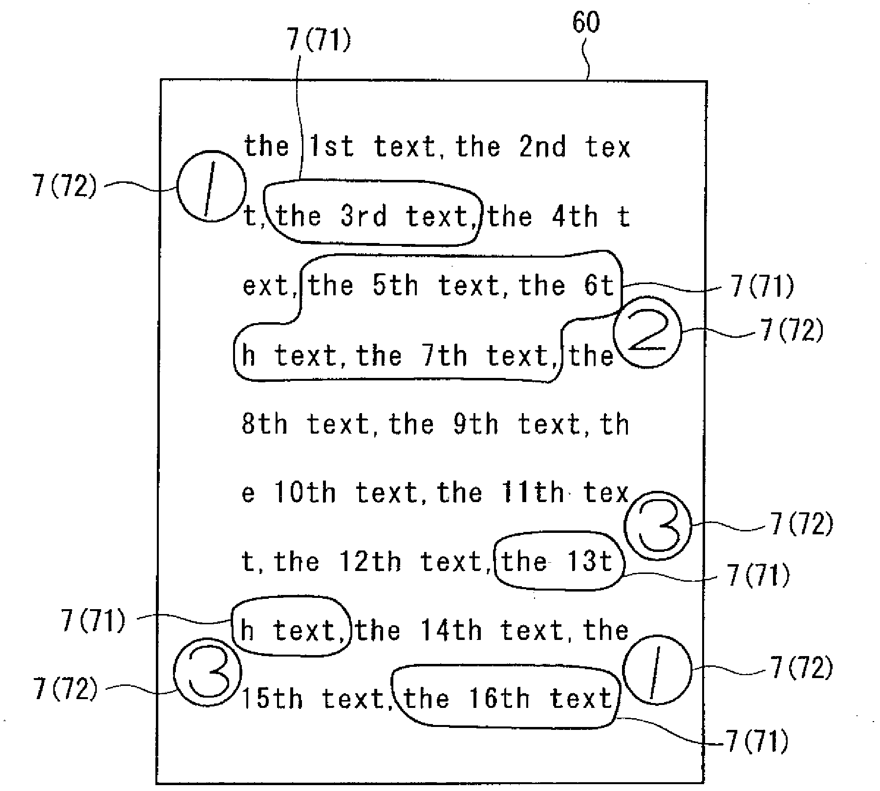
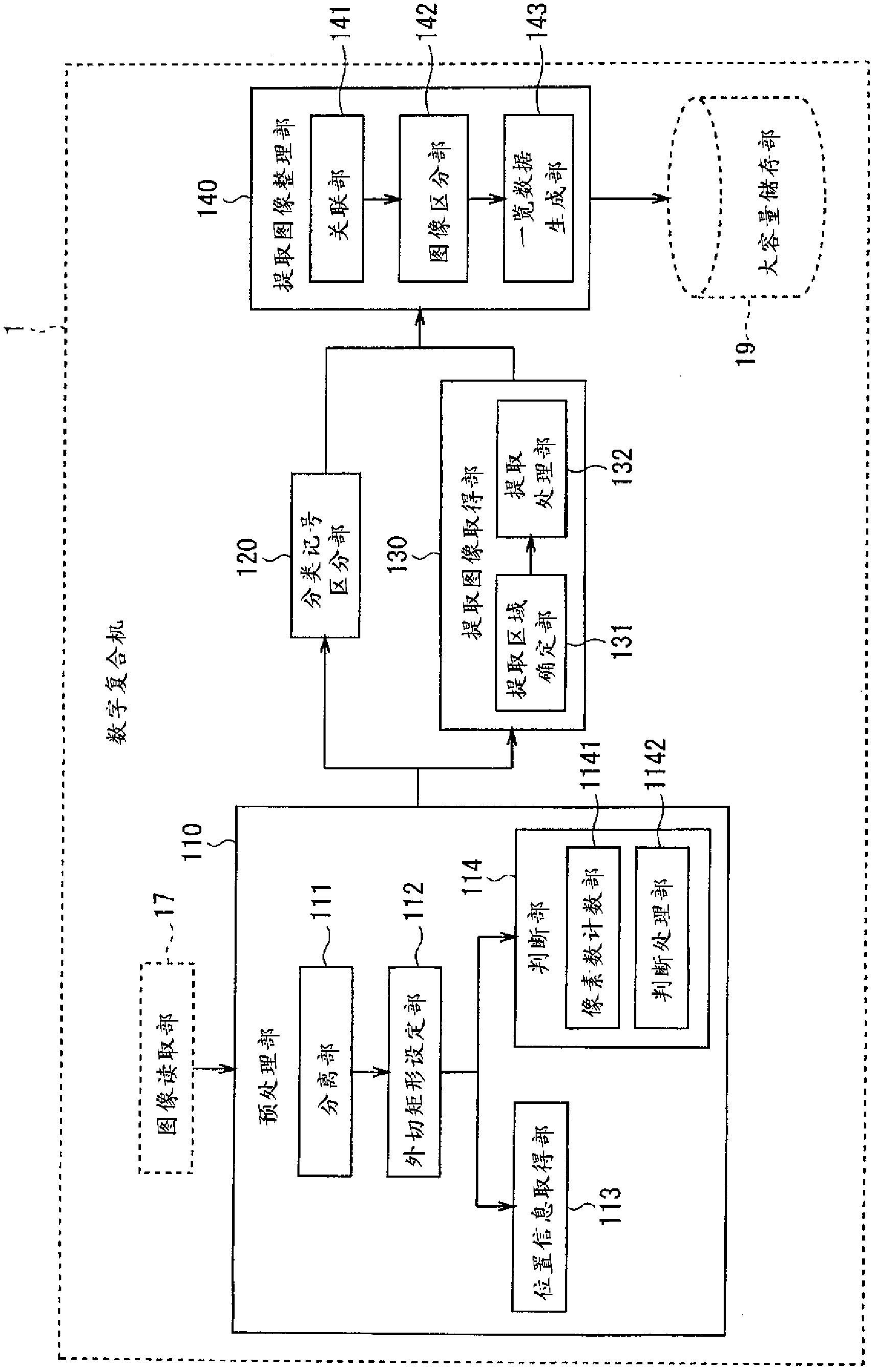
A handwritten area is separated from image data (61) of printed material in which handwriting (7) has been inserted, and the separated handwritten area is identified as an enclosing line (71) or a class symbol (72). An image area (7) enclosed within the handwritten area (7) identified as the enclosing line (71) is extracted and acquired as an extracted image (85). The class symbol (72) is correlated to an enclosing line (71) drawn nearest the class symbol, and the extracted images (85) are classified into groups according to the image areas within the enclosing line (71) correlated to the type of class symbols (71). The grouped images are organized as listed data.

Description

technical field [0001] This application is based on the application No. 2011-009588 filed with the Japan Patent Office on January 20, 2011 as required by Section 119 of the United States Patent Law 35 U.S.C., and the content of the application is incorporated herein by reference. [0002] The present invention relates to a technique for extracting and listing specified parts of image data. Background technique [0003] From the viewpoint of improving operational efficiency and simplifying document management, there are situations where it is desirable to extract only specified parts from printed matter and list them in various cases. For example, in correcting a printed matter, there are cases where the printed document is visually observed, and a part considered to be corrected is marked, and then the marked part is considered to be corrected or not. At this time, if only the marked part is extracted and made into a list (listed), the correction operation can be performed ...

Claims


Application Information

Patent Timeline
Patent Type & Authority Applications(China)
IPC IPC(8): H04N1/00G06K9/20
CPCG06F17/21G06F17/241G06F40/169
Inventor 姜成泰
Owner MURATA MASCH LTD
Learn More