Oil pumping unit

A technology for pumping units and sucker rods, which is applied in mechanical equipment, machines/engines, liquid variable volume machinery, etc., and can solve the problem of manpower pulling the guide wheel bracket, insufficient reversing stability, and large volume of the rewinding wheel, etc. problem, to achieve the effect of reasonable transmission ratio, increased rigidity, and increased mechanical torque

Inactive Publication Date: 2012-07-25
北京宝圣得机械有限公司
View PDF7 Cites 7 Cited by
  • Summary
  • Abstract
  • Description
  • Claims
  • Application Information

AI Technical Summary

Problems solved by technology

Although this pumping unit solves the shortcomings in the above-mentioned application, it needs manpower to pull the guide wheel bracket, which is time-consuming and labor-intensive.
In addition, this kind of pumping unit also has the disadvantages of large volume of rewinding wheel and insufficient stability of commutation

Method used


Image

  • Oil pumping unit
  • Oil pumping unit
  • Oil pumping unit

Examples


Embodiment Construction

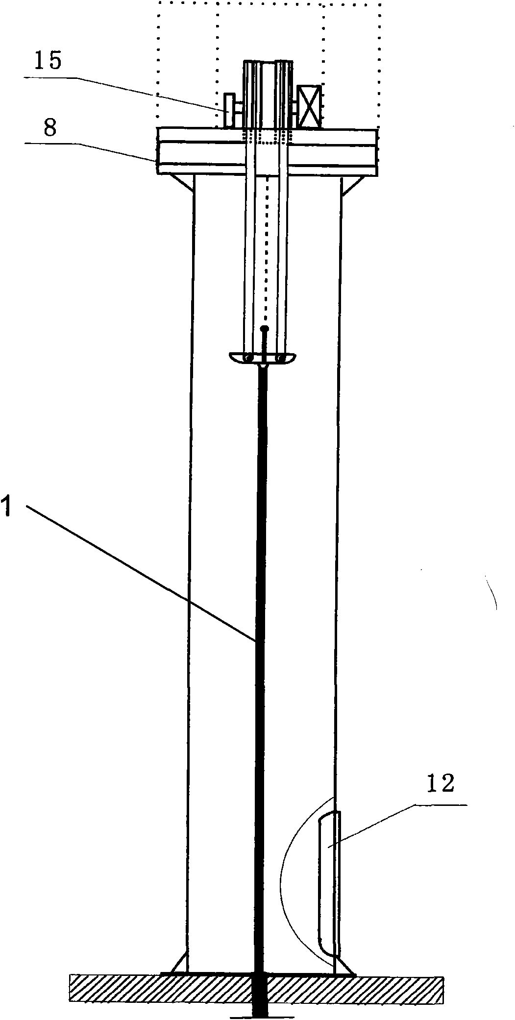
[0057] Figure 1 to Figure 3 A preferred embodiment of the pumping unit of the present invention is shown. see figure 1 , the drum pumping unit in the present invention mainly comprises a vertical main frame 9, a sucker rod 1, a counterweight 11, a platform 8 arranged on the top of the main frame, a motor 27 arranged on the platform 8, multiple The stage reducer 6, the guide wheel 4 and the rewinding wheel 5 cantilevered out of the platform, the motor is connected with the rewinding wheel 5 through the multistage reducer 6 to drive the rewinding wheel. In this embodiment, the main frame 9 has a vertical cavity and a door 14, the control cabinet 12 for controlling the motor is arranged in the vertical cavity, and the counterweight 11 and the counterweight traction rope 16 extend into the vertical cavity indoor. Those skilled in the art should understand that the height of the vertical main frame 9 depends on the length of the stroke when pumping oil. The thickness of the st...


PUM


Abstract

An oil pumping unit comprises a main frame, an oil pumping rod, a counter weight, a platform, a motor, a multilevel speed reducer, a rewinding wheel and a guide wheel, wherein the platform is arranged at the top of the main frame, the motor, the multilevel speed reducer and the rewinding wheel are arranged on the platform, and the guide wheel is pivotally mounted on the platform through a guide wheel support. The motor is connected with the rewinding wheel (5) through the multilevel speed reducer to drive the rewinding wheel, and the rewinding wheel is provided with 2n first holes, 2n second holes and 2m spiral grooves, wherein the first holes are used for a hauling cable of the counter weight, and the second holes are used for a suspension cable of the oil pumping rod. Positions and numbers of the spiral grooves, the first holes and the second holes are configured to enable the suspension cable of the oil pumping rod and/or the hauling cable of the counter weight to be wound in the spiral grooves in a mutual noninterference manner during operation and constantly be opposite in rewinding force moment. The oil pumping unit has the advantages of evident energy saving effect, compact structure and convenience in maintenance. A control system and a control method which are suitable for the oil pumping unit are further provided.

Description

technical field [0001] The invention relates to the field of oil pumping units, in particular to a drum type oil pumping unit. Background technique [0002] Beam crank balanced pumping units are widely used in non-spontaneous well production. This type of pumping unit pumping method has a history of 100 years. Its power consumption is high, the working efficiency is low, the mechanical impact is strong, and the amount of cement and steel is large. In order to reduce the cost of oil extraction, energy saving, consumption reduction and emission reduction have become a major issue of how to increase efficiency in the world's oil extraction industry. [0003] A double drag pumping unit is disclosed in Chinese invention patent application 03102663.X, wherein one or more upper guide wheels are arranged on the top of the support, and the lower guide wheels are also provided on the bottom of the support. The upper guide wheel is fixedly installed on the bracket, and the upper guid...

Claims


Application Information

Patent Timeline
Patent Type & Authority Applications(China)
IPC IPC(8): E21B43/00F04B47/14F04B49/06
Inventor 项援聂圣成
Owner 北京宝圣得机械有限公司
Why Eureka
Try Eureka