Circumferential sampling tool having multiple sample cutters

A cutter and tool technology, applied in the field of circumferential sampling tools, can solve the problem of time-consuming acquisition

Active Publication Date: 2012-07-18
ATOMIC ENERGY OF CANADA LIMITED
View PDF2 Cites 2 Cited by
  • Summary
  • Abstract
  • Description
  • Claims
  • Application Information

AI Technical Summary

Problems solved by technology

This makes it time-consuming to obtain multiple samples from the tube

Method used


Image

  • Circumferential sampling tool having multiple sample cutters
  • Circumferential sampling tool having multiple sample cutters
  • Circumferential sampling tool having multiple sample cutters

Examples


Embodiment Construction

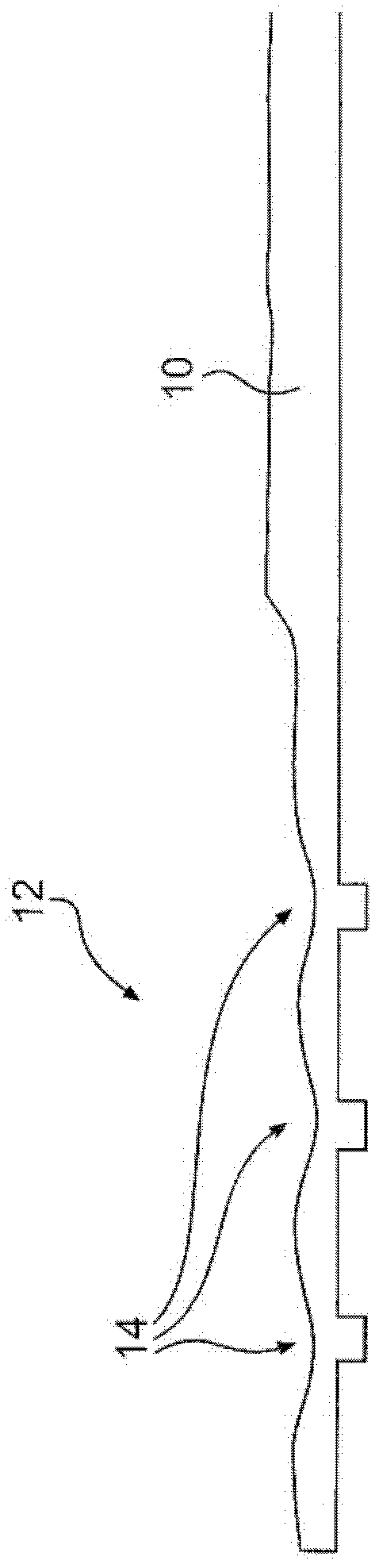
[0048] A circumferential sampling tool of the present invention for obtaining a sample for analysis of deuterium content from a pressure tube of a nuclear reactor will be described. However, it should be understood that the circumferential sampling tool can be used to collect other types of samples from other types of pipes or arcuate surfaces.

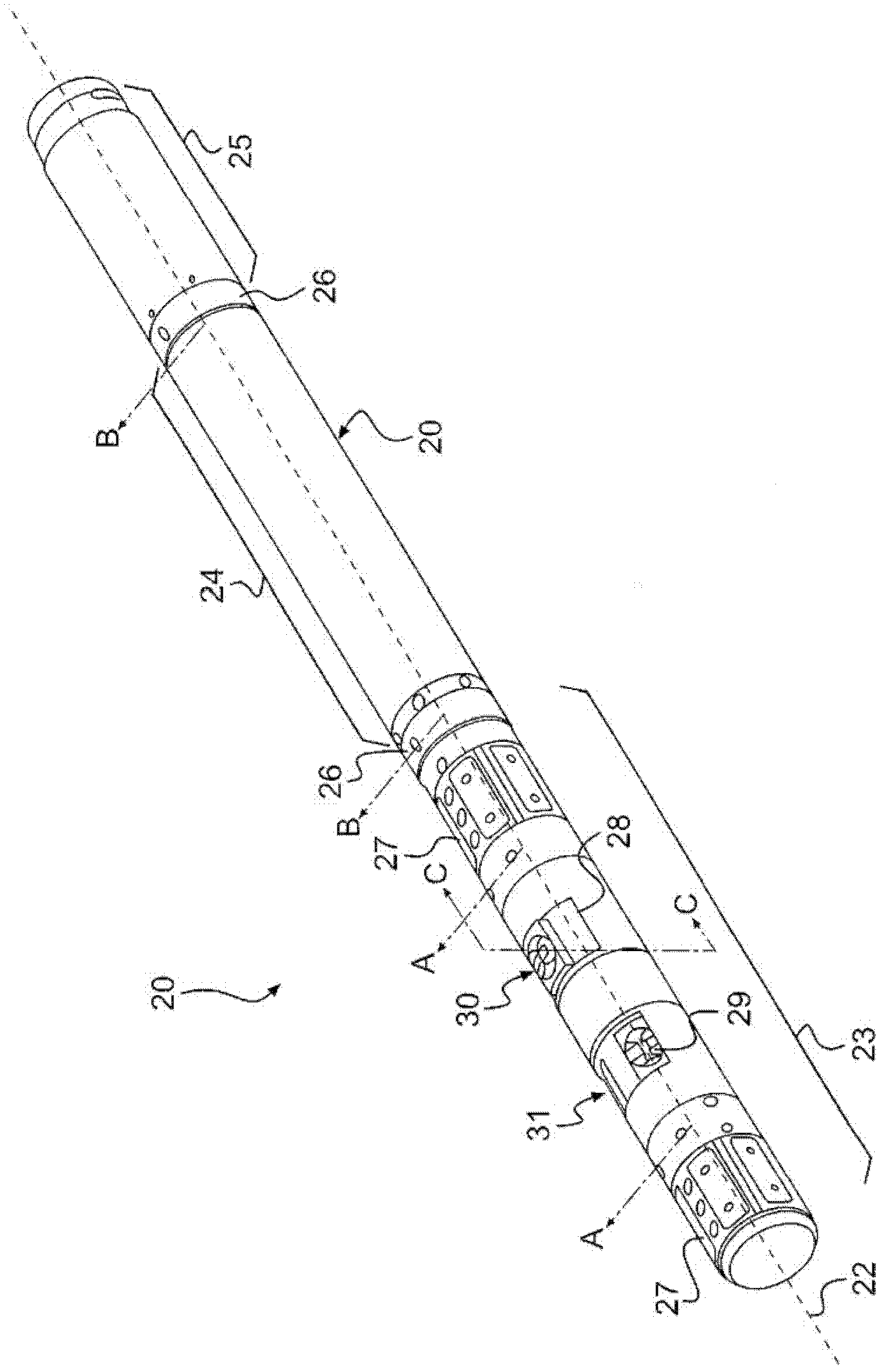
[0049] will refer to figure 2 An embodiment of a circumferential sampling tool 20 is described. The circumferential sampling tool 20 has a cylindrical body 21 with a central axis 22 . The circumferential sampling tool 20 has three main parts: a carriage unit 23 , a drive unit 24 and a hydraulic adjustment unit 25 . The bracket unit 23 , the drive unit 24 and the hydraulic adjustment unit 25 are connected by a flexible joint 26 . Fitting 26 allows circumferential sampling tool 20 to pass through pressure pipe bends without restriction. It should be understood that the central axis 22 of the cylinder 21 shown in the figures corresp...


PUM


Abstract

A circumferential sampling tool for obtaining samples from an interior wall of a tube has a cylindrical body, a shaft disposed in the cylindrical body, a first cutter, a second cutter being disposed at an angle to first cutter, a third cutter, and a fourth cutter being disposed at an angle to the third cutter. The first, second, third and fourth cutters are operatively connected to the shaft for rotation therewith. Each of the cutters is movable radially between a retracted and an extended position in response to rotation of the shaft in order to obtain samples from the tube. A method of obtaining samples from an interior wall of a tube is also disclosed.

Description

technical field [0001] The present invention relates to a circumferential sampling tool having a plurality of sample cutters and methods of using the same. Background technique [0002] One method of estimating the service life of pressure tubes in nuclear reactors, such as CANDU type reactors, requires periodic removal of the tubes. Samples were cut from the removed tubes and analyzed for deuterium content. The deuterium concentration was then used as a measure of the useful life of the remaining pressure tube. This method is very costly due to the long downtime required to remove and replace the pressure tube. [0003] There are a number of difficulties in attempting to provide a technique for sampling "in situ" (without removing the pressure tube). The hard oxide surface and the requirement to obtain sample material from beneath this surface layer makes it difficult to obtain useful samples. In order to maintain the structural integrity of the pipe and avoid detriment...

Claims


Application Information

Patent Timeline
Patent Type & Authority Applications(China)
IPC IPC(8): G01N1/08G21C17/01
CPCG01N1/04G21C17/017G01N2033/0093Y02E30/30G01N1/286G01N2001/2866
Inventor 格雷格·赫萨克理查德·雷詹姆斯·米弛·金
Owner ATOMIC ENERGY OF CANADA LIMITED
Why Eureka
Try Eureka