A flat-panel TV antenna bracket and flat-panel TV antenna system and installation structure

A flat-panel TV and flat-panel antenna technology, applied to antenna support/installation devices, TV system components, TVs, etc., can solve the problems of large space occupation, poor signal reception, inconvenient application, etc., to prevent breakage, Effects of reduced influence and high market competitiveness

Active Publication Date: 2014-10-01
SHENZHEN 1BYONE TECH CO LTD
View PDF4 Cites 0 Cited by
  • Summary
  • Abstract
  • Description
  • Claims
  • Application Information

AI Technical Summary

Problems solved by technology

The hanging method needs to drill holes on the wall. This method is not applicable when there is no background wall or the background wall is not suitable for drilling or there is no background wall, and there are many inconveniences in installation.
For the method of placing under the flat-panel TV through the support, the flat-panel antenna is affected by the radiation of the flat-panel TV, the signal reception is poor, and it takes up a large space, which is not easy to apply

Method used


Image

  • A flat-panel TV antenna bracket and flat-panel TV antenna system and installation structure
  • A flat-panel TV antenna bracket and flat-panel TV antenna system and installation structure
  • A flat-panel TV antenna bracket and flat-panel TV antenna system and installation structure

Examples


Embodiment 1

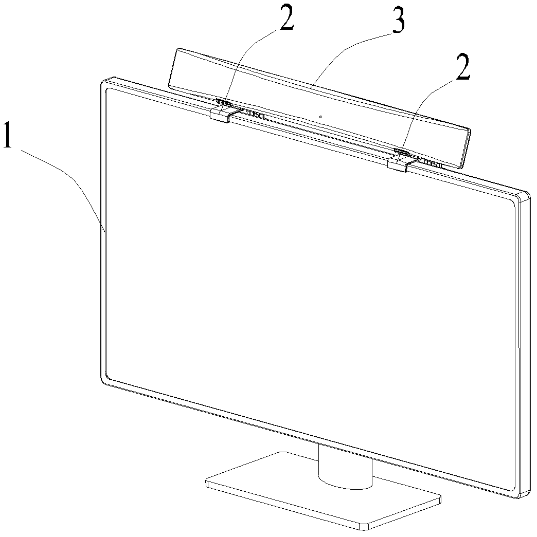
[0031] Embodiment 1: as figure 1 As shown, the present embodiment is a flat-panel TV antenna system, including a flat-panel TV 1, a strip-shaped flat-panel antenna 3 and a support, and the support includes two identical sub-supports 2, and the two sub-supports 2 connect the strip-shaped The flat-panel antenna 3 is horizontally supported on the top 1 of the flat-panel TV, so that the long side direction of the flat-panel antenna 3 supported by the support is parallel to the front edge of the top of the flat-panel TV 1, and the side of the flat-panel antenna 3 forms an angle of 20° with the screen of the flat-panel TV 1, and the The length of the panel antenna 3 is 3 / 4 of the length of the panel TV 1 .

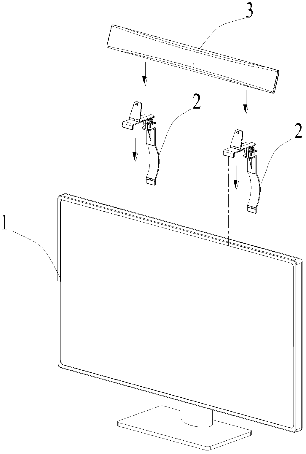
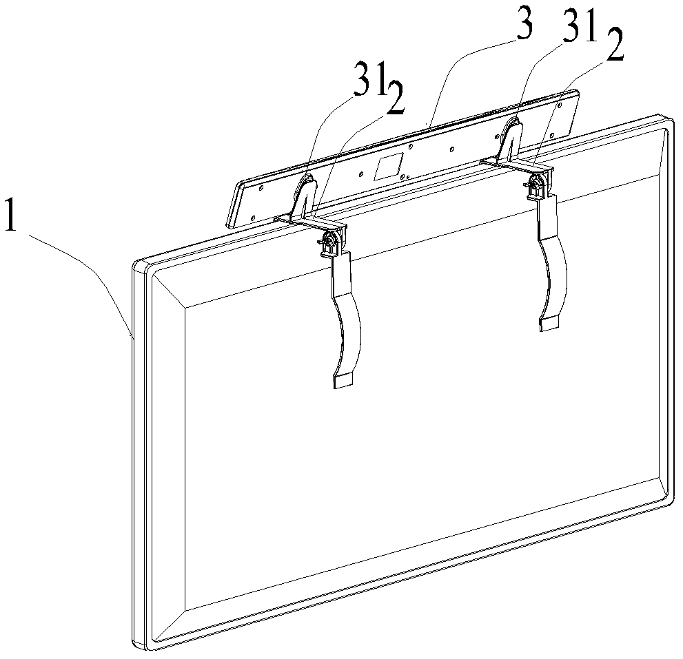
[0032] combine figure 2 and image 3 As shown, the above-mentioned two sub-supports 2 correspond to the two hanging holes 31 on the back of the panel antenna 3 , and the lateral dimension of the sub-support 2 is smaller than the longitudinal dimension, and is in the shape of ...

Embodiment 2

[0038] Embodiment 2: In Embodiment 1, a sub-stent structure of the stent is taken as an example, as Figure 7 As shown, this embodiment includes at least two sub-supports 4 with structures as shown in the figure, the composition of the sub-supports 4 is basically the same as that of the previous embodiment, the difference is that the connecting plate 42 of the sub-supports 4 is perpendicular to the flat plate 414, the plane of the flat-panel antenna installed in this way is parallel to the screen of the flat-panel TV. In order to improve the stability of the structure so that the center of the upper structure of the entire system is relatively rearward after installation, the position of the connecting plate 42 on the flat plate 414 is relatively rearward relative to the previous embodiment.

[0039] As mentioned above, the sub-bracket of the present patent is applicable to any type of existing elongated flat-panel antenna and flat-panel TV, and there is no need to make struct...

Embodiment 3

[0040] Embodiment 3: as Figure 8 As shown, the sub-bracket 2 is used to support a strip-shaped flat-panel antenna 5 having the same size as the flat-panel TV 1 . From the appearance point of view, the appearance of this flat panel TV antenna system is more beautiful and harmonious than that of Embodiment 1.


PUM


Abstract

The invention relates to the field of television antennas, more particularly to a flat-panel television antenna bracket for a flat-panel antenna of a flat-panel television, a flat-panel television antenna system, and a mounting way. The bracket comprises a platform, a hanging part and a support part, wherein the platform is located on the top of the flat-panel television for supporting the flat-panel antenna; the hanging part is located at the front end of the platform and hung on the front edge of the top of the flat-panel television; and the support part is rotatably connected with the platform and supported on the back of the flat-panel television. By application of the flat-panel television antenna bracket disclosed by the invention, mounting of a strip-shaped flat-panel antenna on the top of the flat-panel television without changing the structure of the flat-panel antenna or the flat-panel television can be realized, therefore, the flat-panel television antenna bracket is suitable for the existing general strip-shaped flat-panel antennas and flat-panel televisions. Change of the mounting position of the strip-shaped flat-panel antenna not only enables the strip-shaped flat-panel antenna to be more harmonious with the flat-panel television and to be more beautiful in appearance, but also avoids the influence on the flat-panel antenna due to the radiation of the flat-panel television, so that the flat-panel antenna has better signal receiving effect.

Description

technical field [0001] The invention relates to the field of television antennas, and more specifically relates to a flat-panel television antenna bracket suitable for flat-panel television flat-panel antennas, a flat-panel television antenna system and an installation structure. Background technique [0002] With the widespread use of flat-panel TVs, antennas suitable for flat-panel TVs are also developed. The current flat-panel TV antennas mainly have two types: outdoor and indoor. For the indoor antenna structure suitable for flat-panel TVs, the flat-panel antennas are mainly used. Flat-panel TVs are divided into plate-type structures and strip-shaped structures. On the top of the flat-panel TV, but the signal receiving area is small, the signal receiving effect is poor, and the signal optimization needs to be adjusted through angle adjustment, which increases the complexity of its installation structure. The strip-shaped structure has a large volume and good signal rece...

Claims


Application Information

Patent Timeline
Patent Type & Authority Patents(China)
IPC IPC(8): H01Q1/12H04N5/64
Inventor 杨瑞典
Owner SHENZHEN 1BYONE TECH CO LTD
Why Eureka
Try Eureka