Led module manufacturing method and led module

A technology of light-emitting diodes and manufacturing methods, which is applied to semiconductor devices, light sources, and electric light sources of light-emitting elements, and can solve the problems of high production cost, large volume, and light distribution that is easily affected by alignment errors, and achieve cost and volume savings. Effect

Active Publication Date: 2013-09-25
IND TECH RES INST
View PDF7 Cites 0 Cited by
  • Summary
  • Abstract
  • Description
  • Claims
  • Application Information

AI Technical Summary

Problems solved by technology

[0004] For existing patents, such as the US invention patent 7665862 "LED LIGHTINGFIXTURE", it is to arrange the light-emitting diodes on the long board body that can be turned two-dimensionally, and the board body is set on a support board, and through the flip board The body can change the light-emitting angle of the light-emitting diodes. Although the case can change the light-emitting angle of the light-emitting diodes by adjusting the angles of the support plate and the plate body, it is not possible to adjust each light-emitting diode on the plate to have different angles. In addition, the case as a whole Huge structure, large volume, high production cost
[0005] Another example is the US invention patent 6244728 "LIGHT EMITTING DIODE ASSEMBLYFORUSE AS AN AIRCRAFT POSITION LIGHT", which arranges light-emitting diodes on the top of circuit boards with different angles at the top edge, and then arranges multiple circuit boards at different angles on a substrate , so as to change the light-emitting angle of the light-emitting diode, but because the form of the circuit board in this case is fixed and cannot be changed arbitrarily, the purpose of changing the angle of the light-emitting diode can only be achieved by adjusting the angle of the circuit board on the substrate, and only Adjusting the angles of different circuit boards cannot adjust the angles of each light-emitting diode on the circuit board one by one. In addition, the overall structure of the case is huge and bulky, and the production cost is high
[0006] Another example is Taiwan's new patent M305438 "Structure Improvement of Total Reflection SMD Light-Emitting Diode Bracket", which stamps and forms a plurality of metal pins on a metal sheet, and every two metal pins are matched with a plastic seat, and the plastic seat has a hollow space. The shape functional area is used to set the light-emitting diodes inside, and the metal pins are respectively set in the functional area of ​​the plastic seat, and the two sides of the two metal pins protrude outside the functional area and are buried inside the plastic seat. Although this case can A planar light emitting diode light source module is produced, but the alignment between the rubber base and the metal pin is difficult, the packaging speed is slow, and the light distribution is easily affected by the alignment error. In addition, the position of each rubber base is fixed, that is, the light output of each LED The angles are the same, even though the light emitting angle can be changed by bending the metal sheet, it is not possible to adjust each LED to have a different angle

Method used


Image

  • Led module manufacturing method and led module
  • Led module manufacturing method and led module
  • Led module manufacturing method and led module

Examples


Embodiment Construction

[0058] The technical means and effect that the present invention uses to achieve the purpose will be described below with reference to the accompanying drawings, and the embodiments listed in the following drawings are only auxiliary descriptions, in order to facilitate the understanding of the technical solutions of the present invention, but the present invention The technical means are not limited to the enumerated drawings.

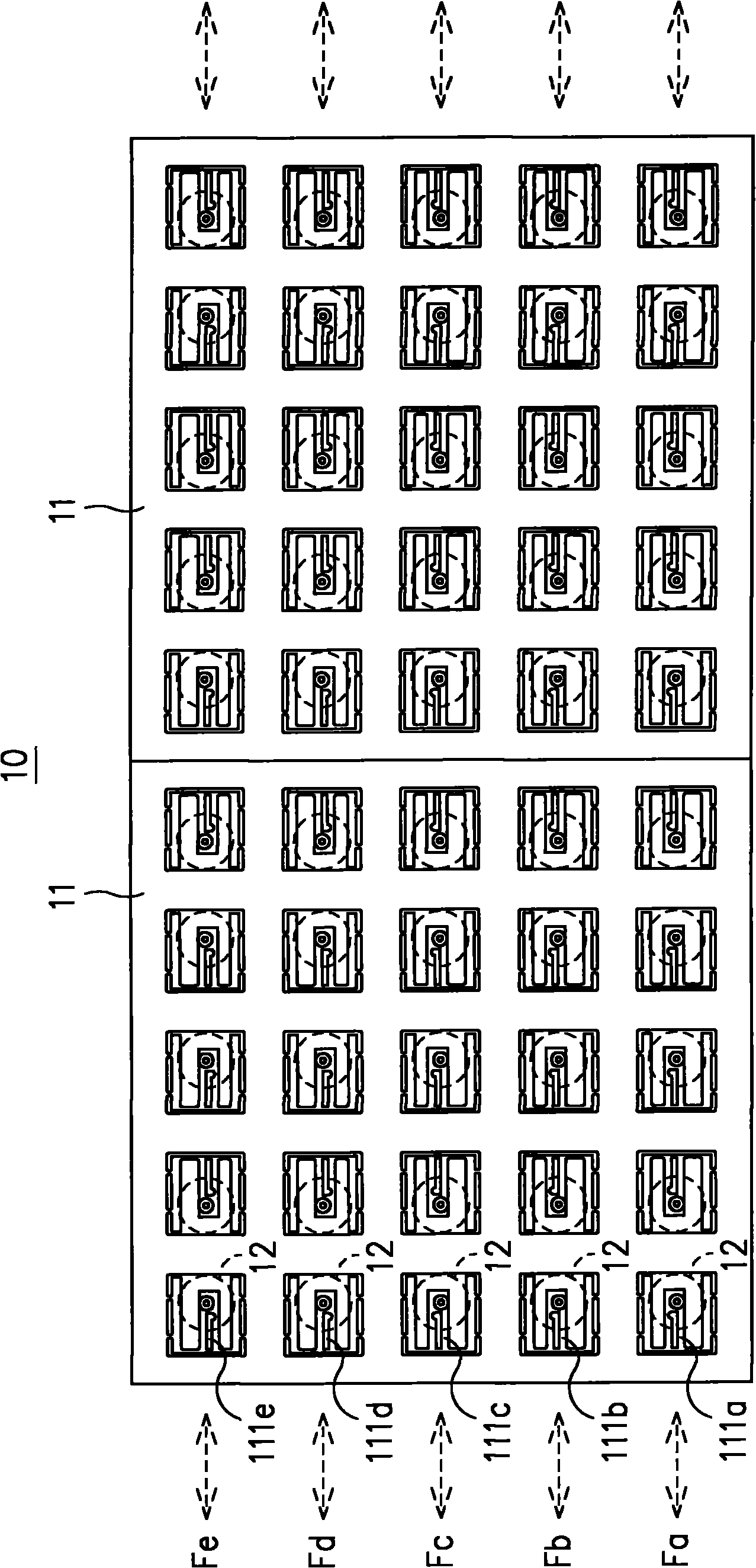
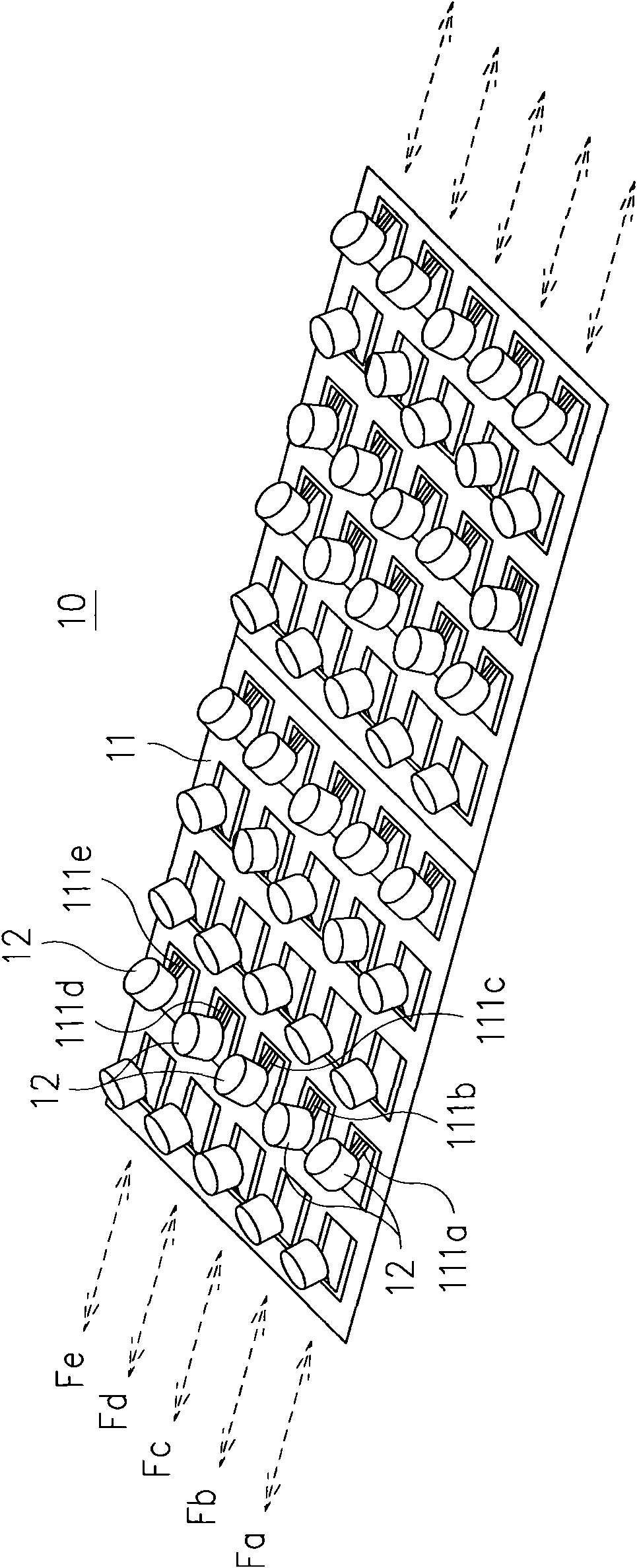
[0059] see Figure 5 to Figure 7 As shown, the manufacturing process of the light-emitting diode module provided by the present invention includes the following steps:

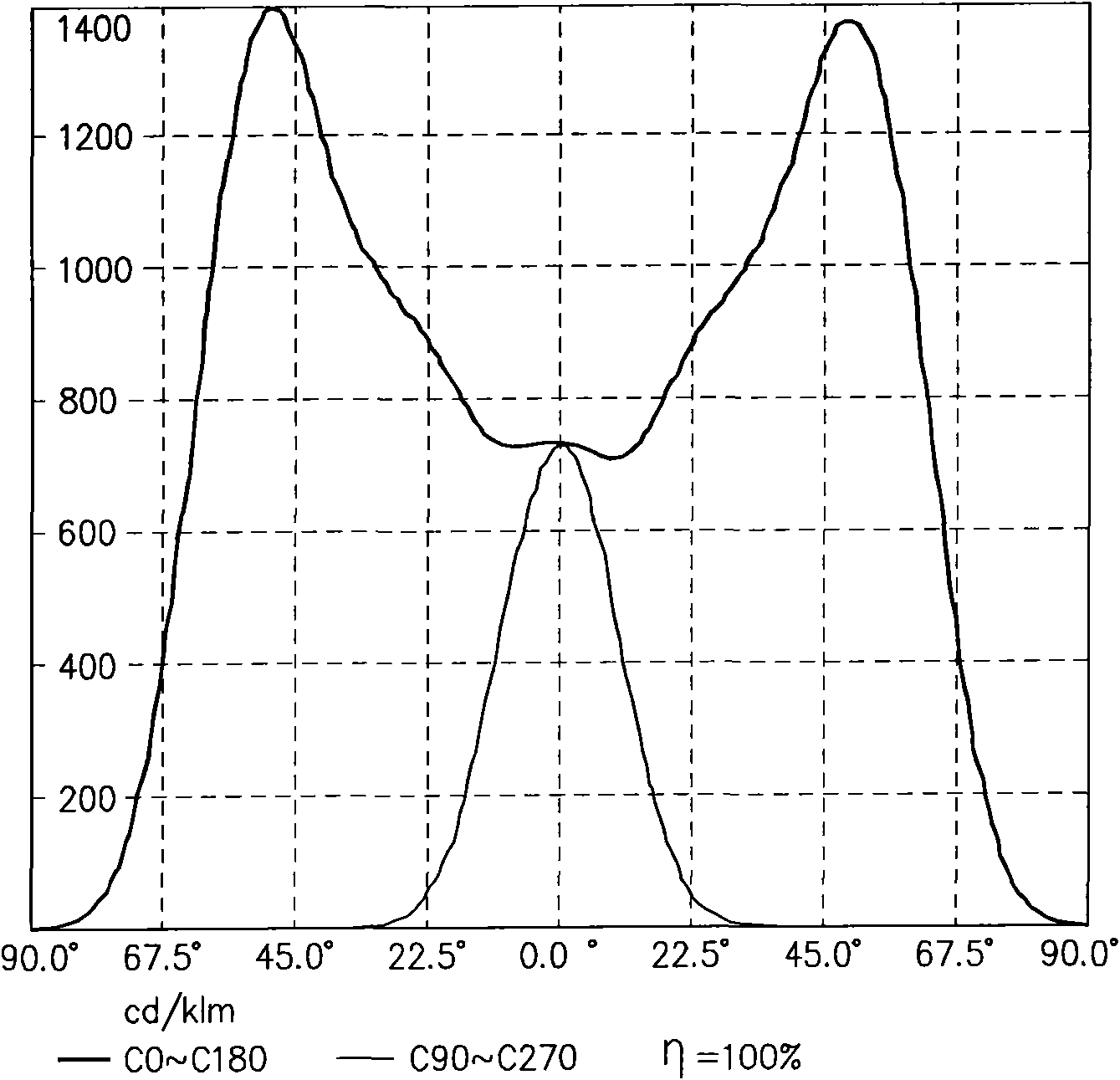
[0060] Step 1: First, according to the required light distribution curve, calculate the light output angle configuration of multiple LEDs and obtain multiple sets of data sets. Each data set corresponds to a light-emitting diode, and each data set includes a light-emitting diode. The rotation angle of the diode on the horizontal plane and the included angle between the light-emitting...


PUM


Abstract

The invention provides an LED module manufacturing method and an LED module. In the invention, according to a required distribution curve flux, the configuration of light emitting angle of a plurality of LEDs can be calculated and multiple data groups are obtained. Each data group is corresponding to an LED and includes a rotary angle of an LED relatively to a horizontal plane and an included angle of a light outgoing face of the LED and the horizontal plane. At least two data groups have different rotary angles and at least two data groups have different included angles. According to the rotary angles of the data groups, a plurality of loading sheets are arranged on a lead support. Each loading sheet is provided with an LED. Thus, the lead support is provided with a plurality of the LEDs. According to the included angle, the loading sheets are bent, thereby making light outgoing angles of the LEDs on the loading sheets meeting the calculated data groups.

Description

technical field [0001] The invention relates to a method for manufacturing a light-emitting diode module and the light-emitting diode module, in particular to a light distribution curve that meets user needs without additional light control elements, which can greatly reduce the asymmetry of production costs and time The light-emitting diode module has the advantages of high target light projection efficiency, high flexibility in lamp design, small lamp size and energy saving. Background technique [0002] Because light-emitting diodes (LEDs) have the advantages of small size, high luminous efficiency, long life and rich color changes, more and more applications of light-emitting diodes, but light-emitting diode light-emitting elements are different from traditional light-emitting elements. Insufficient, so LED lamps mostly use multiple LEDs arranged on a plane to provide sufficient luminous intensity, and LEDs are directional light sources, so LED lamps are usually arranged...

Claims


Application Information

Patent Timeline
Patent Type & Authority Patents(China)
IPC IPC(8): F21S8/00F21V19/00F21W131/103F21Y101/02F21Y105/16F21Y115/10
Inventor 林修任林建宪彭耀祈陈効义蔡祯辉
Owner IND TECH RES INST
Why Eureka
Try Eureka