Gas extraction bored well and forming method

A gas drainage and drilling technology, applied in drilling equipment and methods, gas discharge, drilling equipment, etc., can solve problems such as blockage of screen pipe channels, deformation of screen pipes, and influence on normal gas drainage, so as to reduce damage and The effect of clogging

Inactive Publication Date: 2012-07-11
HUAINAN MINING IND GRP
View PDF7 Cites 8 Cited by
  • Summary
  • Abstract
  • Description
  • Claims
  • Application Information

AI Technical Summary

Problems solved by technology

For the gas drainage drilling formed by the existing method, according to the bottom hole video detection, it is found that when the hole depth is less than 500m, the screen pipe is seriously deformed due to the impact of mining
This is due to the fact that there are multiple screen holes arranged on the screen wall, the shear strength and compressive strength are low, and the rock strata that are easily moved and deformed after mining will be damaged, resulting in serious blockage of the screen channel, which seriously affects the normal operation of gas drainage. conduct

Method used


Image

  • Gas extraction bored well and forming method
  • Gas extraction bored well and forming method
  • Gas extraction bored well and forming method

Examples


Embodiment 1

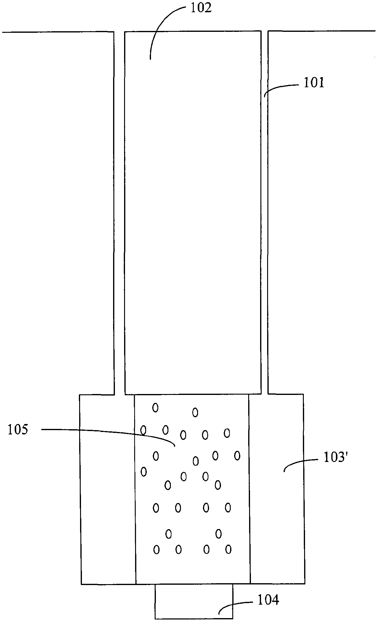
[0028] figure 1 The gas drainage drilling provided for Embodiment 1 of the present invention includes a casing section and a screen section. The casing section includes a casing section wellbore 101 and a casing 102. The screen section includes a screen section wellbore 103' and a screen pipe 105. Wherein, the screen pipe 105 is located in the well hole 103' of the screen pipe section, and the diameter of the well hole 103' of the screen pipe section is larger than the diameter of the well hole 101 of the casing section. distance. The so-called "safety distance" is the distance that can reduce the impact on the screen pipe when the rock stratum moves after the coal seam is mined.

[0029] Preferably, a bottom well hole 104 located directly below the well hole of the screen section is also included.

[0030] Preferably, the distance between the outer wall of the screen and the hole wall of the wellbore of the screen section is greater than or equal to 200 mm. For example, wh...

Embodiment 2

[0040] Figure 5 The flow chart for forming a gas drainage well provided in Embodiment 2 of the present invention may specifically be a method for forming a gas drainage well provided in any embodiment of the present invention.

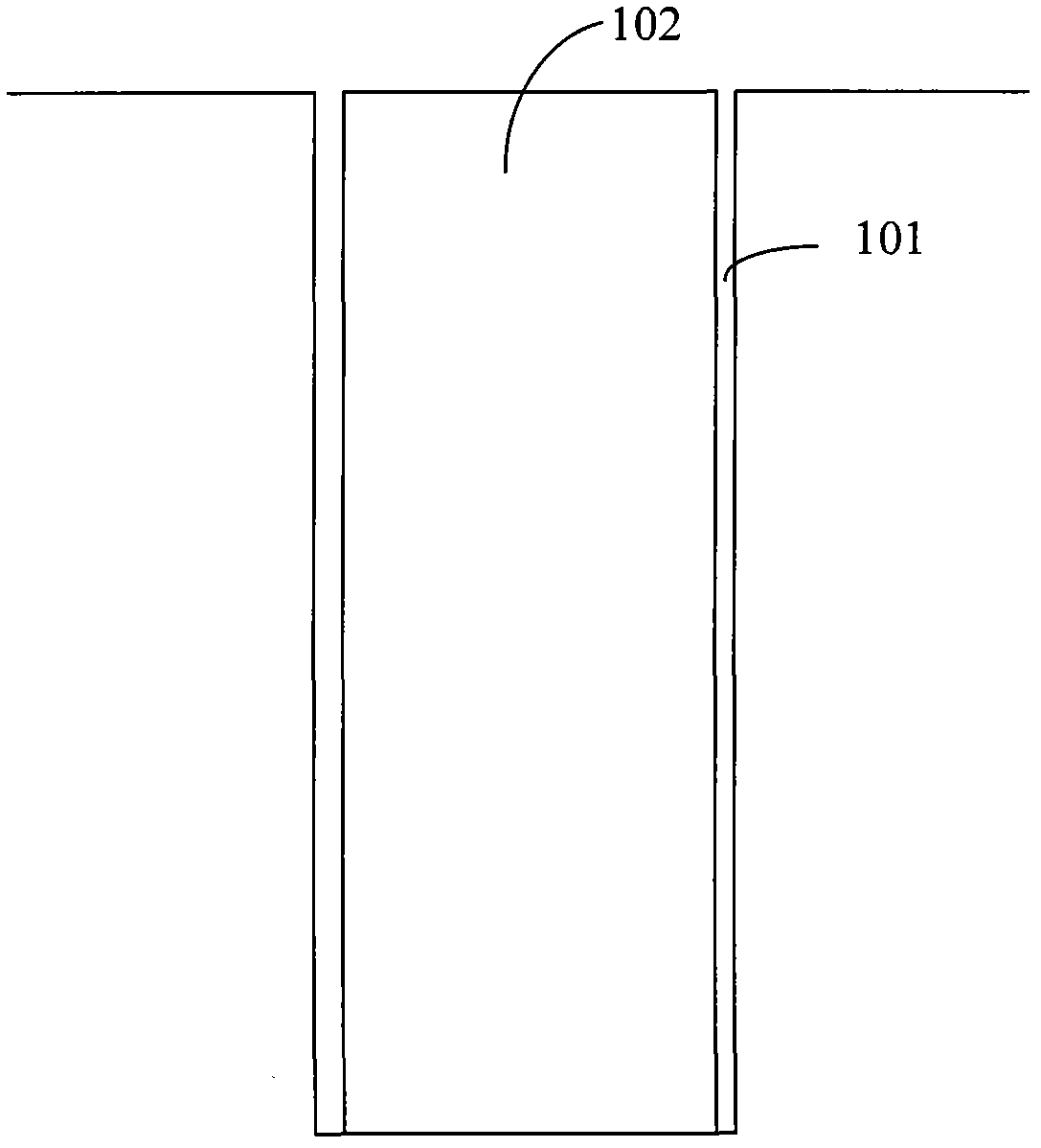
[0041] In step 501, a casing section wellbore is formed.

[0042] In step 502, a casing is placed and cemented in the casing section wellbore.

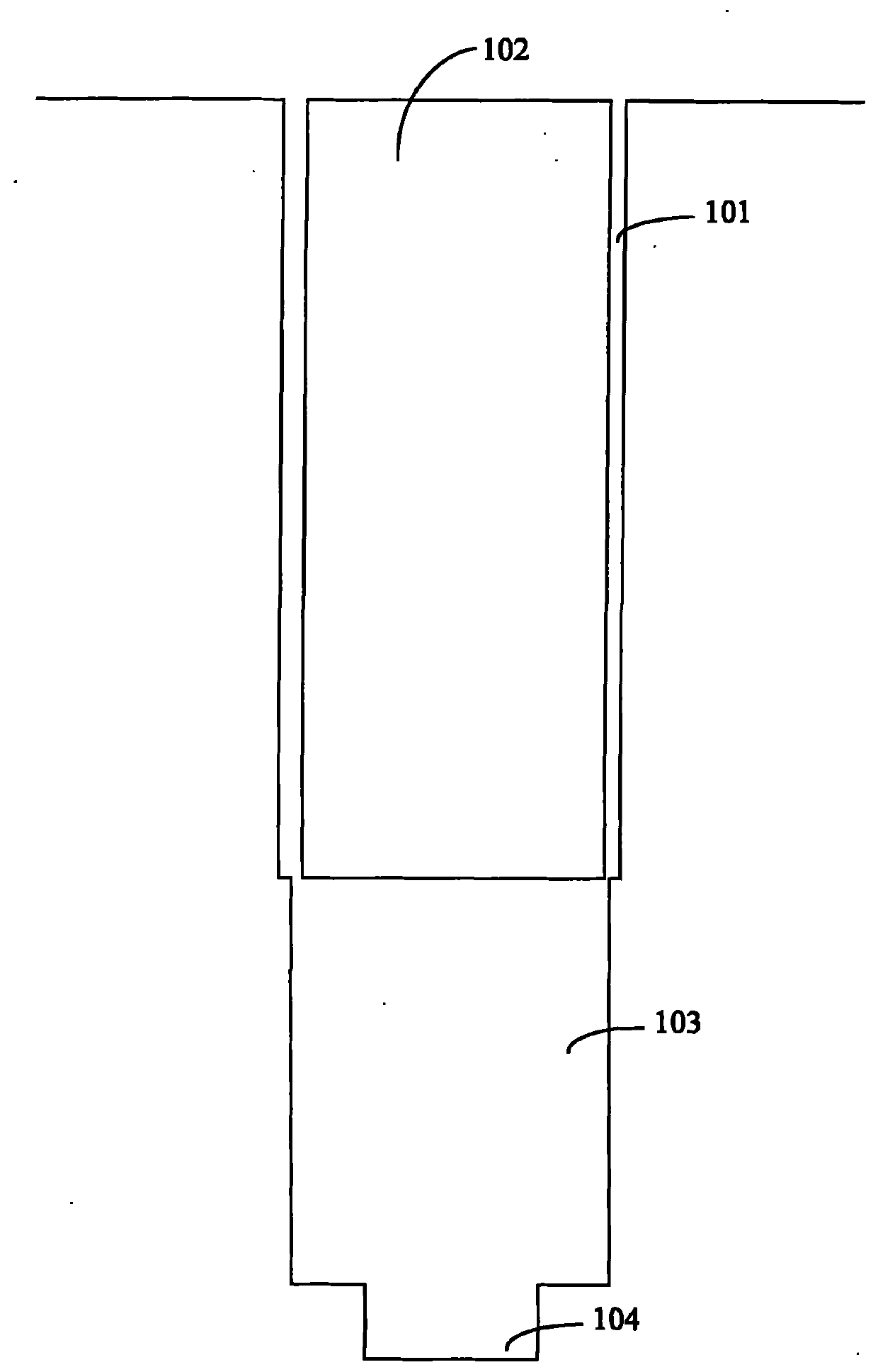
[0043] In step 503, drilling is performed right below the wellbore of the casing section, and reaming is performed to enlarge the diameter of the borehole below the casing section to be larger than the diameter of the wellbore of the casing section, so as to form the wellbore of the screen section.

[0044] In step 504, the screen is put into the wellbore of the screen section, and there is a safe distance between the outer wall of the screen and the hole wall of the wellbore of the screen section.

[0045] The value of the safety distance is preferably greater than or equal to 200mm. The diameter of the s...


PUM


Abstract

The invention discloses a gas extraction bored well and a forming method. The bored well comprises a casing section and a sieve tube section. The casing section comprises a casing and a casing section well hole, and the sieve tube section comprises a sieve tube and a sieve tube section well hole; and the sieve tube is located in the sieve tube section well hole, the diameter of the sieve tube section well hole is larger than that of the casing section well hole, and a safety distance is reserved between the outer wall of the sieve tube and the hole wall of the sieve tube section well hole. The method includes forming the casing section well hole; placing the casing in the casing section well hole and cementing; drilling a hole right below the casing section well hole, chambering, and expanding the diameter of the drilled hole below the casing section well hole to be larger than that of the casing section well hole so as to form the sieve tube section well hole; and placing the sieve tube into the sieve tube section well hole, and reserving the safety distance between the outer wall of the sieve tube and the hole wall of the sieve tube section well hole. According to the gas extraction bored well and the forming method, a certain gas outlet channel can be reserved after the sieve tube is affected by extraction, and accordingly smooth gas extraction is ensured.

Description

technical field [0001] The invention relates to drilling technology, in particular to a gas drainage drilling and formation method. Background technique [0002] At present, in oil or coalbed gas well drilling projects, most of them adopt the method of drilling and setting casing. The basic process of the formation method of gas drainage drilling is: drilling, running casing, and then cementing, and repeating the above operations until the predetermined depth is reached. After the above process is completed, a gas drainage screen is placed under the casing, and a real gas drainage pipe is placed inside the casing to complete the entire gas drainage drilling structure. [0003] However, in the current gas drainage drilling, since the diameter of the drill bit used in the next stage of drilling needs to be smaller than the diameter of the casing placed in the previous stage, the inner diameter of the next stage of the pipe is smaller than that of the previous stage. , the "t...

Claims


Application Information

Patent Timeline
Patent Type & Authority Applications(China)
IPC IPC(8): E21B43/00E21B17/00E21B43/08E21B7/04E21B7/20E21B7/28E21F7/00
Inventor 汪敏华赵俊峰白国基陈建黄晖黄碧石程志忠
Owner HUAINAN MINING IND GRP
Why Eureka
Try Eureka