
Stitching instrument with cutter and cutter component of stitching instrument with cutter

A technology of cutter assembly and stapler, which is applied to dissection instruments, surgical fixation nails, etc., can solve the problems of uneven cutting edges, inconvenience, and laborious cutting tissue.

Active Publication Date: 2013-12-04
B J ZH F PANTHER MEDICAL EQUIP
View PDF3 Cites 0 Cited by
  • Summary
  • Abstract
  • Description
  • Claims
  • Application Information

AI Technical Summary

Problems solved by technology

[0005] However, the existing stapler instruments with a cutter are all based on the original linear stapler, and a cutter is fixed in the middle of the two rows of staples. The cutting direction of the cutter is perpendicular to the direction of the suture line. Under the action of the thrust, make a single longitudinal movement with the nail pusher towards the direction of the nail seat, and cut off the tissue and the pad blade under the tissue by the instantaneous vertical thrust
The advantage of this structure is that the structure is simple, and the disadvantage is that it is laborious to cut the tissue, the cutting edge is not neat, and the staples are easy to tilt in the direction of the cutter, resulting in poor staple formation and easy leakage of the suture.
[0006] This shows that the above-mentioned existing band-knife stapler and its cutter assembly obviously still have inconvenience and defects in structure and use, and need to be further improved urgently.

Method used


Image

  • Stitching instrument with cutter and cutter component of stitching instrument with cutter
  • Stitching instrument with cutter and cutter component of stitching instrument with cutter
  • Stitching instrument with cutter and cutter component of stitching instrument with cutter

Examples


Embodiment Construction

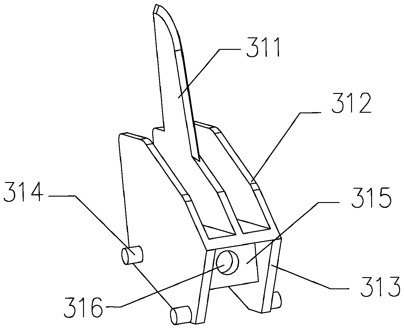
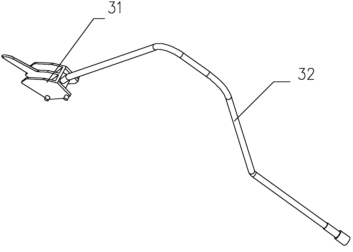
[0036] A cutter assembly of a stapler with a knife in the present invention includes a cutter slider 31 , a knife-connecting wire rope 32 , a guide plate 33 and a fixing block 34 .

[0037] Among them, see figure 1 As shown, a cutter 311 is arranged in the middle of the upper part of the cutter slider 31, and firing pieces 312 are arranged on both sides of the cutter 311. The firing pieces 312 extend downwards to form a positioning plate 313, and the outside of the positioning plate 313 is provided with a positioning pin 314, and the positioning plate The inner side of 313 is provided with a wire rope installation block 315, and the wire rope installation block 315 is provided with an installation hole 316 along the front and rear direction of the cutter slider 31.

[0038] Preferably, as shown in the figure, the cutter slider 31 is integrally formed. The cutting knife 311 can be selected with a single-side arc-shaped knife face. The firing piece 312 can adopt a polygonal st...


PUM


Abstract

The invention relates to a stitching instrument with a cutter and a cutter component of the stitching instrument with the cutter. The cutter component comprises a cutter slider, a cutter connecting steel wire rope, guiding plates and a fixing block; the cutter slider is provided with the cutter, a triggering plate, a positioning plate, positioning pins, a steel wire rope mounting block and a mounting hole; one end of the cutter connecting steel wire rope penetrates through the mounting hole and is fixed; each guiding plate is provided with a guiding groove, the guiding grooves correspond to the positioning pins, and the cutter slider is slidably mounted between the two guiding plates via the positioning pins; and the fixing block is mounted below the guiding plates and the cutter slider. The cutter component of the stitching instrument with the cutter is mounted in an inner cavity of a nail bin, and the cutter connecting steel wire rope of the cutter component is connected with a traction mechanism. The stitching instrument with the cutter is applicable to the nail bin with the small longitudinal space, and is simple in structure, convenient in assembly and safe in use. The triggering force of the stitching instrument is low, stitching nails are formed well, stitching and cutting actions are simultaneously realized by the effect of tension of the traction mechanism, the cutting direction of the stitching instrument is parallel to the direction of a stitching thread, and accordingly the stitching instrument is more applicable to popularization and application.

Description

technical field [0001] The invention relates to a surgical medical instrument, in particular to a stapler with a knife and a cutter assembly thereof. Background technique [0002] In surgical operations, medical staplers have become an indispensable auxiliary medical device in the process of suturing human tissue. With the development of medicine and product research and development, more and more multifunctional staple products are used in clinical practice. One of the few tools. The application of medical stapler has many advantages such as less bleeding during operation, shorter operation time, reduction of manual operation error, avoidance of infection, and quick recovery of postoperative function. [0003] A commonly used product in medical staplers is a linear cutting stapler, which is mainly used to suture the openings of cavity tissues. The sutures are neat and very firm, and bleeding from the sutures is not easy to occur. The original linear stapler only had the ...

Claims


Application Information

Patent Timeline
Patent Type & Authority Patents(China)
IPC IPC(8): A61B17/072A61B17/3209
Inventor 李学军刘青
Owner B J ZH F PANTHER MEDICAL EQUIP
Learn More