
Image trapping method and system

An image and trapping technology, applied in the field of image trapping methods and systems, can solve the problems of not distinguishing the translucent part of the image, the trapping area or the border of the trapping area is not smooth, etc., and achieve the effect of good trapping effect.

Active Publication Date: 2012-07-04
FOUNDER INTERNATIONAL CO LTD +1
View PDF2 Cites 0 Cited by
  • Summary
  • Abstract
  • Description
  • Claims
  • Application Information

AI Technical Summary

Problems solved by technology

[0004] In view of the defects existing in the prior art, the object of the present invention is to provide an image trapping method and system, which solves the problem that the existing trapping method does not distinguish the translucent part of the image, resulting in redundant trapping areas or irregularities at the borders of the trapping areas. smooth technical issues

Method used


Image

  • Image trapping method and system
  • Image trapping method and system
  • Image trapping method and system

Examples


Embodiment Construction

[0044] The present invention is aimed at the problem that in the existing trapping method, if there is a transparent area in the image to be trapped, if the opaque part in the trapping area is not distinguished, the problem of redundant trapping areas will be generated, or the semi-transparent part and the semi-transparent part are strictly distinguished. The problem that opaque parts will cause unsatisfactory border trapping results is proposed. Through the present invention, images with transparent regions can produce better trapping effects when trapping.

[0045] The present invention will be further described in detail below in conjunction with the accompanying drawings and specific embodiments.

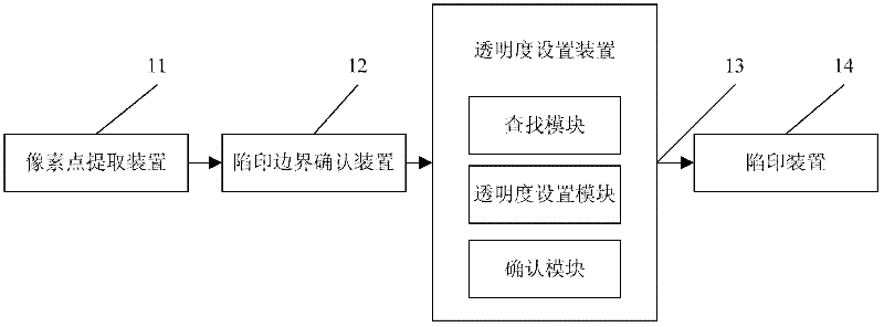
[0046] image 3 A structural block diagram of an image trapping system of the present invention is shown, as can be seen from the figure, the system mainly includes:

[0047] Pixel extraction device 11: used to select the image to be trapped, and extract the pixels in the image...


PUM


Abstract

The invention discloses an image trapping method and a system, which belong to the field of image trapping. The method comprises the steps of: traversing all pixel points in each column in an image to be trapped to search for the boundary of an area to be trapped; and setting the transparency of the pixel points in the image and trapping the image. Aiming at the problems that in the current trapping method, semitransparent part is not distinguished to generate unnecessary trapping areas, and semitransparent and non-transparent parts are strictly distinguished to cause undesirable effect of trapping boundary, a setting method of transparent parts in the image is proposed. The method used to trap the image generates better trapping effect and solves the above problem in the prior art.

Description

technical field [0001] The invention relates to the field of image trapping in image processing, in particular to an image trapping method and system. Background technique [0002] The transparency attribute of the image is similar to the opacity value of the Path in AI (adobe illustrator), each pixel in the image has an opacity opacity, then the ink dot percentage of the point is equal to the ink dot percentage of the pixel point × opacity+ ink dot percentage of the pixel corresponding to the pixel position in the lower layer × (1-opacity). We define the pixel part of the image whose opacity is 0 as the fully transparent part, the pixel part whose opacity is 1 is the opaque part, and the part whose opacity is between 0 and 1 is the semi-transparent part. The fully transparent part of the image has no dot percentage, and the color of the underlying object is completely displayed, and the opaque part of the image completely displays the color of the upper layer image, and th...

Claims


Application Information

Patent Timeline
IPC IPC(8): H04N1/58
Inventor 张琴尹慧
Owner FOUNDER INTERNATIONAL CO LTD
Learn More