
Direct current shunt release applicable to operation in series connection with direct current relay

A technology of shunt release and series operation, which is applied in the direction of circuits, electric switches, electrical components, etc., and can solve the problem that the DC shunt release cannot work in series with the DC intermediate relay, the DC intermediate relay cannot work normally, and the DC intermediate relay Low voltage and other problems, to achieve the effect of widening the scope of use, high reliability, and stable pulse signal

Inactive Publication Date: 2014-04-09
CHANGZHOU INST OF TECH
View PDF10 Cites 0 Cited by
  • Summary
  • Abstract
  • Description
  • Claims
  • Application Information

AI Technical Summary

Problems solved by technology

[0003] Existing DC shunt releases are all short-time working systems, and cannot be connected (operated) to the power supply for a long time, and the power-on time generally cannot exceed 1 second, otherwise the coil in the shunt electromagnet coil is easily burned; in addition, if The DC intermediate relay is connected in series with the DC shunt release. Due to the series voltage division, the voltage obtained by the DC intermediate relay is too low, and the DC intermediate relay cannot work normally, so the DC shunt release cannot work in series with the DC intermediate relay.

Method used


Image

  • Direct current shunt release applicable to operation in series connection with direct current relay
  • Direct current shunt release applicable to operation in series connection with direct current relay
  • Direct current shunt release applicable to operation in series connection with direct current relay

Examples


Embodiment 1

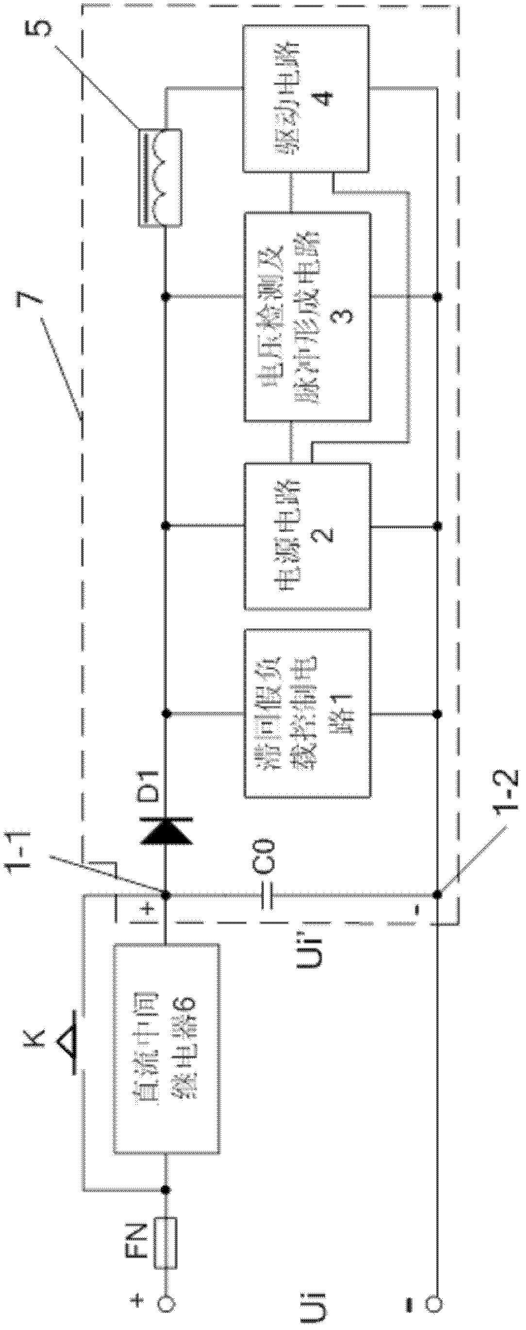
[0020] See Figure 1-2 In this embodiment, the DC shunt release adapted to work in series with the DC intermediate relay, the positive end of the total input voltage Ui is connected from the DC intermediate relay, and the DC intermediate relay is connected to the DC shunt release 7's first contact 1-1, its second contact 1-2 is connected to the negative end of the input total voltage Ui, the DC input voltage obtained by the DC shunt release is Ui', the button switch K connected in parallel with the DC intermediate relay.

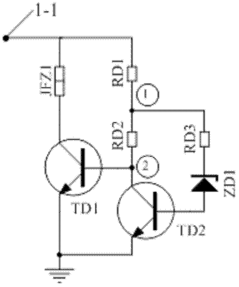
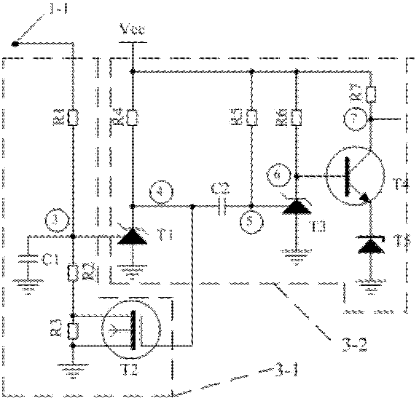
[0021] The DC shunt release includes: first and second contacts 1-1, 1-2, drive circuit 4, shunt electromagnet coil 5, voltage detection and pulse forming circuit 3 and hysteresis dummy load control circuit 1; The hysteresis preload control circuit 1 is suitable for disconnecting the preload resistor JFZ1 when the DC input voltage Ui' obtained by the DC shunt release 7 is greater than 70% of the rated voltage Ue of the DC shunt release 7 , when the DC inpu...

Embodiment 2

[0033] See Figure 1-3 , the working method of the DC shunt release 7 described in the above-mentioned embodiment 1, comprising:

[0034] A. When the button switch K connected in parallel to the DC intermediate relay 6 is turned on, the total DC input voltage Ui of the series circuit composed of the DC intermediate relay and the DC shunt release and the DC voltage of the DC shunt release The input voltage Ui' is equal, and provides access voltage to the hysteresis dummy load control circuit 1, voltage detection and pulse forming circuit 3, and shunt electromagnet coil 5 in the DC shunt release; when the DC input When the voltage Ui' is greater than 70% of the rated voltage Ue of the DC shunt release, the dummy load resistor JFZ1 in the hysteresis dummy load control circuit 1 is disconnected, and the voltage detection and pulse forming circuit 3 detects After the DC input voltage Ui' is greater than 70% of the rated voltage Ue, a single pulse signal lasting 50-60 ms is generat...


PUM


Abstract

The invention relates to a direct current shunt release applicable to operation in series connection with a direct current intermediate relay. A first contact is respectively connected with current input ends of a hysteresis dummy load control circuit, a power circuit, a voltage detection and pulse formation circuit and a shunt electromagnet coil; a second contact is respectively connected with grounding ends of the hysteresis dummy load control circuit, the power circuit, the voltage detection and pulse formation circuit and a driving circuit; the voltage detection and pulse formation circuit generates a single-pulse signal; and the single-pulse signal is amplified by the driving circuit and then connected to the other end of the shunt electromagnet coil to turn on the shunt electromagnet coil. The direct current shunt release can operate in series connection with the direct current intermediate relay, the using range of the direct current shunt release is expanded, the shunt electromagnet coil cannot be burnt down even if the shunt electromagnet coil is energized for a long time, and the direct current intermediate relay which is in series connection with the direct current shunt release has a reliable operating voltage.

Description

technical field [0001] The invention relates to a DC shunt release suitable for working in series with a DC intermediate relay. Background technique [0002] The shunt release is used to receive the remote control voltage and is the core component to realize the "remote control" opening of the low-voltage circuit breaker. For example, in civil buildings where fire protection requires a power outage circuit, a circuit breaker with a shunt release can be selected. The fire alarm system can remotely control the opening of the circuit breaker through modules or cables in the fire center. [0003] Existing DC shunt releases are all short-time working systems, and cannot be connected (operated) to the power supply for a long time, and the power-on time generally cannot exceed 1 second, otherwise it is very easy to burn the coil in the shunt electromagnet coil; in addition, if The DC intermediate relay is connected in series with the DC shunt release. Due to the low voltage obtain...

Claims


Application Information

Patent Timeline
Patent Type & Authority Patents(China)
IPC IPC(8): H01H71/24H01H9/54
Inventor 吴志祥
Owner CHANGZHOU INST OF TECH
Learn More