
Wind turbine with hydraulic blade pitch system

A blade variable pitch and wind turbine technology, applied in the direction of wind power generators, engines, wind power generation, etc., can solve the problems of increased operating time percentage, maintenance and repair, etc., and achieve the effects of size reduction, rapid adjustment, and cost reduction

Active Publication Date: 2014-10-29
VESTAS WIND SYST AS
View PDF10 Cites 0 Cited by
  • Summary
  • Abstract
  • Description
  • Claims
  • Application Information

AI Technical Summary

Problems solved by technology

Therefore, the operating time percentage can be increased without requiring more maintenance and repairs

Method used


Image

  • Wind turbine with hydraulic blade pitch system
  • Wind turbine with hydraulic blade pitch system
  • Wind turbine with hydraulic blade pitch system

Examples


Embodiment Construction

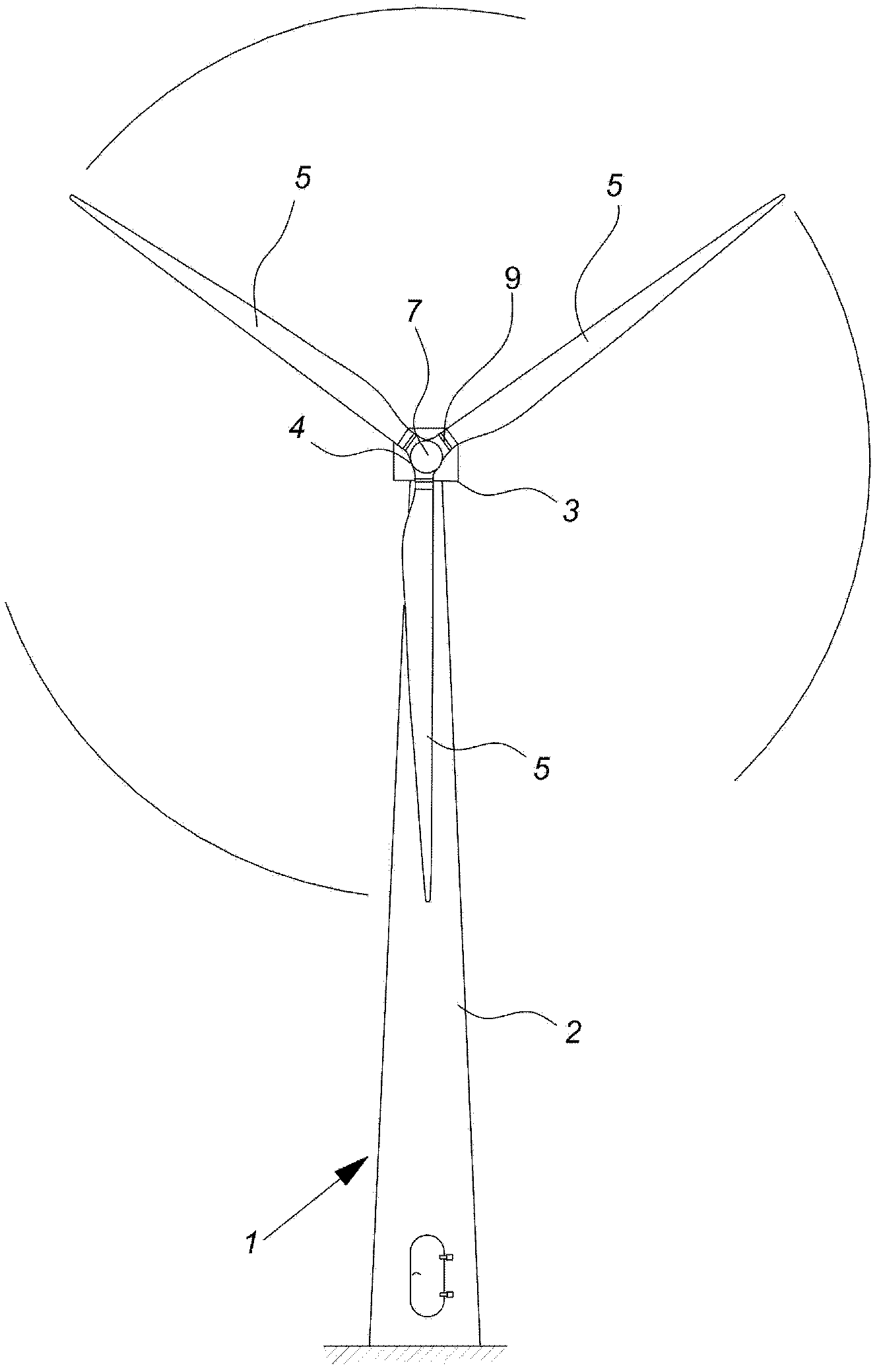
[0083] figure 1 A wind turbine 1 is shown comprising a tower 2 and a wind turbine nacelle 3 positioned on top of the tower 2 . A wind turbine rotor 4 comprising three wind turbine blades 5 is connected to the nacelle 3 by a low speed shaft protruding in front of the nacelle 3 .

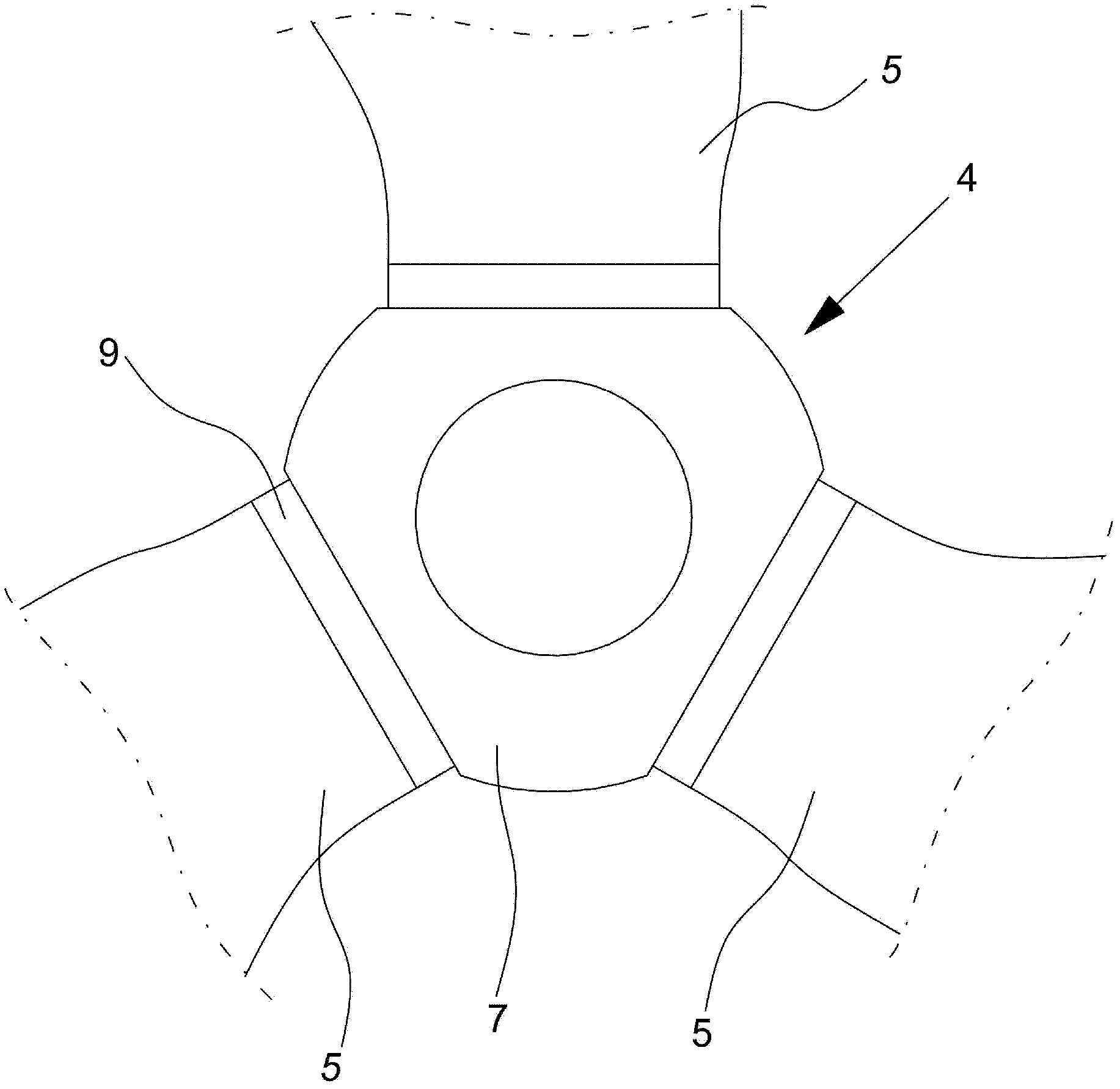
[0084] figure 2 A wind turbine rotor 4 comprising a hub 7 and three blades 5 is shown seen from the front.

[0085] As shown are pitch bearings 9 which are arranged between the blade 5 and the hub 7 to enable the rotation of the blade 5 about its longitudinal axis and to transmit forces mainly from three different sources. The blade 5 (and of course the bearing 9 itself) is under the constant influence of gravity. The direction of gravity changes depending on the position of the blade 5 , resulting in different loads on the pitch bearing 9 . When the blade is in operation, the bearing 9 is also subject to centrifugal forces which mainly generate axial tension on the bearing 9 . Finally the beari...


PUM


Abstract

A wind turbine (1) is disclosed having a rotor (4) with at least two blades (5) and a blade pitch system (6) for controlling the pitch angle of said blades (5), the blade pitch system (6) comprising for each of said blades a hydraulic blade pitch drive (8) and at least two valves (22a, 22b, 22c) mutually connected in parallel for controlling a flow of liquid to the hydraulic blade pitch drive (8) for that blade (5), wherein said valves (22a, 22b, 22c) each comprises an arrangement for providing a variable flow of liquid.

Description

[0001] The invention relates to a wind turbine comprising a rotor with adjustable blades and a hydraulic blade pitch system for controlling the pitch angle of the blades. Background technique [0002] Wind turbines having a blade pitch system for adjusting the pitch angle of the blades have been known for many years, usually using electric pitch drives or hydraulic pitch drives. Early embodiments of hydraulic pitch drives are disclosed, for example, in United Technologies patents US 4,348,155 and US 4,352,634. The hydraulic valves used to control the fluid flow to the linear hydraulic actuators are disclosed as switching valves, ie valves that operate in on-off mode and the pitch torque is not adjustable. [0003] In patent EP1 835 174 B1 of Robert Bosch GmbH a wind turbine is disclosed with a hydraulic pitch drive in which the flow of liquid is controlled by means of switching valves, The plurality of switching valves are arranged in parallel and are operable in different co...

Claims


Application Information

Patent Timeline
Patent Type & Authority Patents(China)
IPC IPC(8): F03D7/04
CPCY02E10/723F05B2270/1074F05B2260/70F05B2270/604F05B2260/79F03D7/0264F03D7/0224F05B2270/506F05B2260/74Y02E10/72
Inventor J·L·安德森J·B·马德森
Owner VESTAS WIND SYST AS
Learn More