
Framework circuit breaker arc extinguishing chamber

A frame circuit breaker and arc extinguishing chamber technology, which is applied to circuit breaker parts and other directions, can solve the problems of affecting the breaking capacity of the circuit breaker, small grid area, and unsatisfactory arc extinguishing effect, and achieves extended length and increased grid area. The effect of large, elongated arcs

Active Publication Date: 2014-12-03
CHANGSHU GUORUI TECH CO LTD
View PDF5 Cites 2 Cited by
  • Summary
  • Abstract
  • Description
  • Claims
  • Application Information

AI Technical Summary

Problems solved by technology

[0003] In the traditional arc extinguishing chamber, the area of ​​the grid is too small due to the too long ventilation channel of the arc extinguishing cover. The actual application proves that the arc extinguishing effect is not ideal, which seriously affects the breaking capacity of the circuit breaker.

Method used


Image

  • Framework circuit breaker arc extinguishing chamber
  • Framework circuit breaker arc extinguishing chamber
  • Framework circuit breaker arc extinguishing chamber

Examples


Embodiment Construction

[0017] The present invention will be described in detail below with reference to the accompanying drawings and examples.

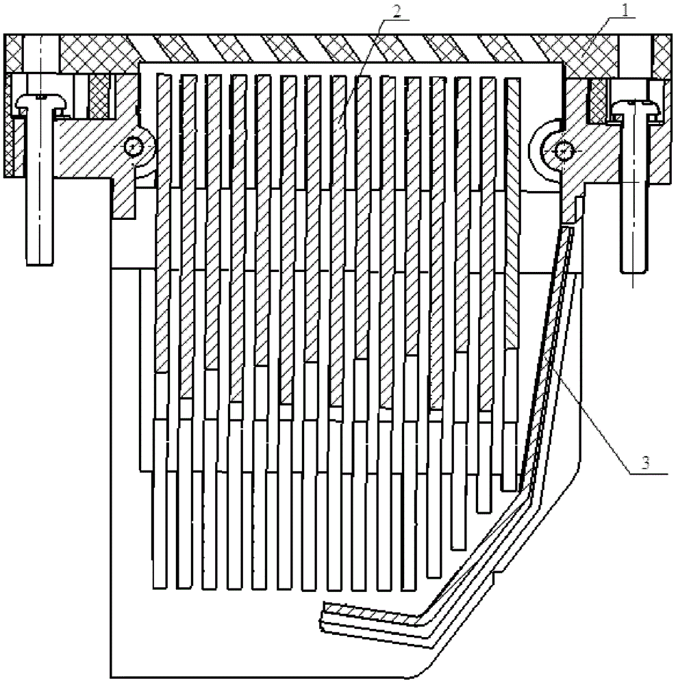
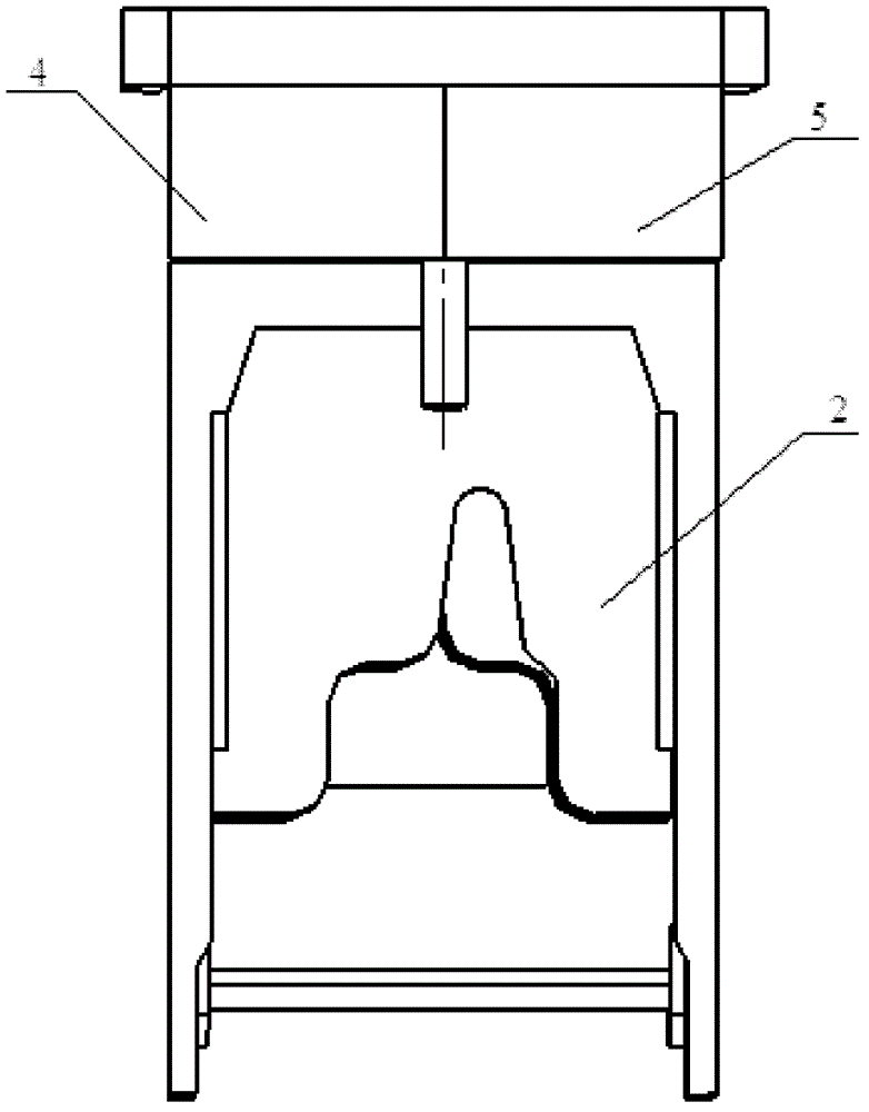
[0018] The invention provides a frame circuit breaker arc extinguishing chamber, such as figure 1 shown. The arc extinguishing chamber includes an arc shield 1 , a grid 2 , an arc striker 3 , a first arc shield 4 and a second arc shield 5 . The tops of the first and second arc shields have protrusions in the middle for connection with the arc shield 1 . The arc starting piece 3 is a bent sheet structure, and one side is vertical, and the other side is inclined to the lower left, and forms an obtuse angle with the vertical surface. The arc starting piece 3 is inserted into the slot at the rightmost end of the two arc partition walls.

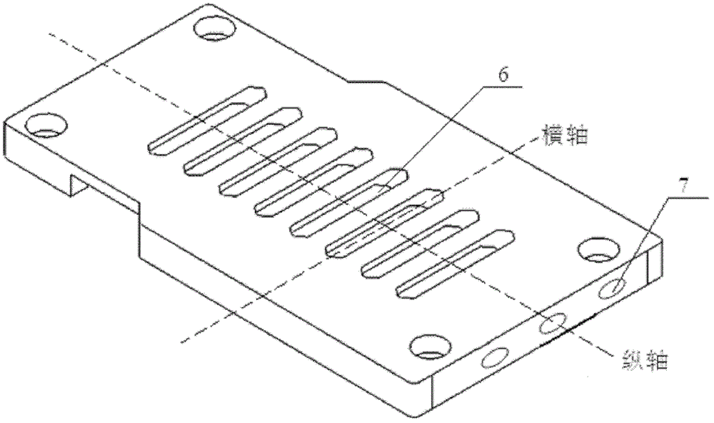
[0019] The structure of the arc shield 1 is as follows image 3 shown. The arc shield is made of insulating material, and there are grooves on both sides of its bottom surface, which are used for docking with the protrusi...


PUM


Abstract

The invention discloses a framework circuit breaker arc extinguishing chamber, which belongs to low-voltage electric appliance equipment and comprises an arch isolation cover, a grid plate, an arc striking plate, a first arc isolation wall and a second arc isolation wall, wherein the arc isolation cover is fixedly arranged on the top of the first arc isolation wall and the second arc isolation wall, and in order to increase the exhaust area and to simultaneously control the exhaust directions of the arc isolation cover, more than one inclined exhaust hole is processed along the transverse axial line of the arc isolation cover on the premise of ensuring the intensity requirements. Two ends of the grid plate are respectively connected with the inner walls of the first arc isolation wall and the second arc isolation wall and are in staggered placement in the arc extinguishing chamber in a way that one end is positive and the other end is reverse. In order to lengthen the electric arc through pulling, asymmetric grooves are processed in the middle position of the lower end of the grid plate, simultaneously, in order to increase the length of the grid plate, the top of the grid plate uses the condition that the top is not in contact with the inner wall of the arc isolation cover as the limit, the bottom of the grid plate uses the condition that the bottom is not in contact with the inner wall of the arc striking plate as the limit, and the grid plate is in step-type arrangement along the inclined surface of the arc striking plate. In the practical application, after the arc extinguishing chamber in the structure is adopted, the short circuit breaking capability of a circuit breaker is improved from the original 80kA to 120kA.

Description

technical field [0001] The invention relates to an arc extinguishing chamber of a frame circuit breaker, which belongs to low-voltage electrical equipment. Background technique [0002] During the action of the circuit breaker with load breaking, the voltage between the contacts causes the air medium to discharge and form an arc. Therefore, in switches such as circuit breakers and contactors, arc extinguishing chambers are usually provided to extinguish the arc, thereby ensuring the safe operation of electrical equipment. [0003] In the traditional arc extinguishing chamber, the area of ​​the grille is too small due to the too long air passage of the arc shield. The actual application proves that the arc extinguishing effect is not ideal, which seriously affects the breaking capacity of the circuit breaker. Contents of the invention [0004] In view of this, the present invention provides an arc extinguishing chamber of a frame circuit breaker with good arc extinguishing...

Claims


Application Information

Patent Timeline
Patent Type & Authority Patents(China)
IPC IPC(8): H01H73/18
Inventor 龚瑞良吴宏杨建东王炫
Owner CHANGSHU GUORUI TECH CO LTD
Learn More