
Direct power control method of voltage source PWM (pulse width modulation) rectifier system

A power control and rectifier technology, applied in the field of electrical transmission, can solve the problems of poor steady-state performance of the PWM rectifier system, high harmonic content of grid-side current, etc., and achieve good dynamic and static characteristics, optimized performance, and optimized control effects

Inactive Publication Date: 2014-12-10
SOUTHEAST UNIV
View PDF2 Cites 0 Cited by
  • Summary
  • Abstract
  • Description
  • Claims
  • Application Information

AI Technical Summary

Problems solved by technology

[0006] The DPC method with a voltage sensor structure can be divided into a single switch table and a double switch table structure. The single switch table introduces a large number of zero vectors and is limited by the ability to simultaneously adjust active and reactive power decoupling by using one switch table. The current still has high harmonic content, and there is a period of reactive power runaway area in each cycle; the essence of the double switch table structure is to use two switch tables in turn to control active power and reactive power separately, improving The dynamic response of the PWM rectifier system is affected, but it will lead to poor steady-state performance of the PWM rectifier system

Method used


Image

  • Direct power control method of voltage source PWM (pulse width modulation) rectifier system
  • Direct power control method of voltage source PWM (pulse width modulation) rectifier system
  • Direct power control method of voltage source PWM (pulse width modulation) rectifier system

Examples


Embodiment

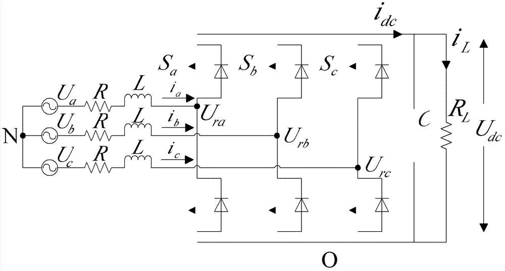
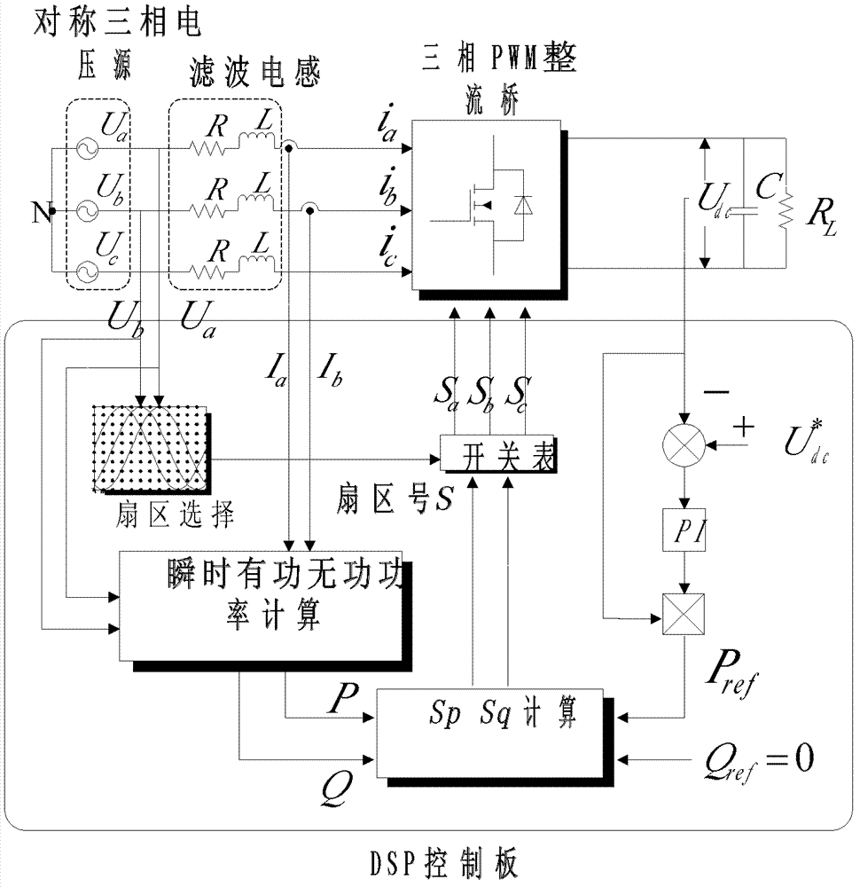
[0033] Example: by figure 2 As shown in the structure, the simulation model is built in the MATLAB / simulink environment, and the parameters are as follows: The initial value of the load resistance is R L =22Ω, five 110Ω resistors are connected in parallel, two resistors are cut off when the load changes suddenly, R L ’=110 / 3Ω; filter inductance L=7mH; filter capacitor C=3000μF; current inner loop PI regulator proportional constant K p =0.8, integral constant K i =0.2;H p =H q = 4W, S p = S q =4. The simulation results are shown in Figure 5. The current waveform of phase A on the grid side is sinusoidal. The actual system uses a three-phase three-wire isolation transformer. In order to correspond to the actual measurement results, Figure 5(a) shows the BC phase line voltage and A phase current, and the A phase current leads the BC phase line voltage. 90°, it can be seen from Figure 5(b) that the active and reactive power input by the rectifier is decoupled, the reactiv...


PUM


Abstract

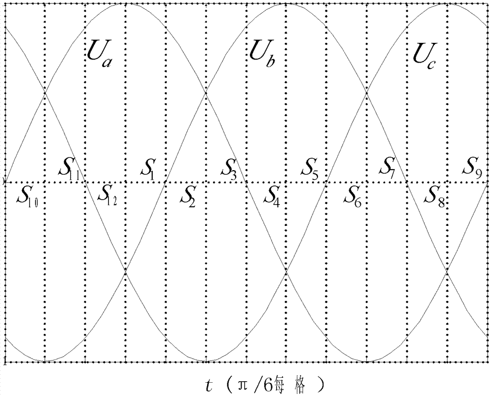
The invention provides a direct power control method of a voltage source PWM (pulse width modulation) rectifier system. Based on an inner-loop power and outer-loop voltage control method adopted in a DPC (data processing control) method, set values of active power and reactive power are compared with actual values, and a voltage vector is selected by querying a switch list to control the on-off state of the PWM rectifier. According to the control method provided by the invention, a state variable marking the active power and the reactive power is added, the location of a space vector is redefined and a segmented switch list is constructed, thus enhancing the decoupling control on the active power and the reactive power and the response capability, and improving the power factor of the rectifier. The calculation and experiment results show that the grid side input current is sine and the instantaneous power dynamic and static control characteristics of the system are better.

Description

technical field [0001] The invention relates to a direct power control method of a voltage-type PWM rectifier system, belonging to the technical field of electric transmission. Background technique [0002] With the development of power electronics technology and digital signal processing technology, various converter devices based on pulse width modulation (PWM) technology have been widely used in the industrial field. The PWM rectifier has the advantages of sinusoidal current on the grid side, grid-connected unit power factor, and convenient bidirectional flow of energy, which truly realizes the "green conversion" of electric energy. Various circuit configurations and control algorithms targeting sinusoidal currents have also been proposed. In the early 1990s, Tokuo Ohnishi proposed a control method that applied the concept of instantaneous active power and reactive power to the three-phase PWM converter system. Subsequently, scholars such as Toshihiko Noguchi conducted r...

Claims


Application Information

Patent Timeline
Patent Type & Authority Patents(China)
IPC IPC(8): H02M7/219
Inventor 林明耀韩愚拙林克曼朱信舜骆皓
Owner SOUTHEAST UNIV
Learn More