
Thickness gauge for rolling mill and running gear of thickness gauge

A technology of walking device and thickness gauge, which is applied in the direction of length measuring device, metal rolling, metal rolling, etc. It can solve problems such as unstable air pressure, influence of rolling mill production, shaking instability, etc., so as to improve quality and improve thickness measurement Accuracy, the effect of optimizing the walking characteristics

Inactive Publication Date: 2012-06-13
SOUTHWEST ALUMINUM GRP
View PDF8 Cites 2 Cited by
  • Summary
  • Abstract
  • Description
  • Claims
  • Application Information

AI Technical Summary

Problems solved by technology

[0003] The walking mode of the existing rolling mill thickness gauge is the driving mode driven by the cylinder. The disadvantage of the cylinder is that many factors such as the stability of the air pressure, the load situation, and the walking road conditions will affect the uniformity and stability of the walking.
[0004] Therefore, the cylinder of the existing thickness gauge is pushed to walk, and many unfavorable factors cause the air pressure to be unstable, causing the thickness gauge to jog forward during the walking process, and the walking cannot be positioned accurately; in addition, the stroke of the rolling mill thickness gauge is about 1.5 meters, and the stroke of the cylinder is relatively long , and the cylinder is small, the piston rod is slender, and the cylinder pushes and walks, which brings a lot of inconvenience to daily maintenance
[0005] Therefore, how to solve the problem that the rolling mill thickness gauge is not in place and shaking and unstable during the production process, so as to avoid the impact on the rolling mill production, has become an important technical problem to be solved urgently by those skilled in the art

Method used


Image

  • Thickness gauge for rolling mill and running gear of thickness gauge
  • Thickness gauge for rolling mill and running gear of thickness gauge
  • Thickness gauge for rolling mill and running gear of thickness gauge

Examples


Embodiment Construction

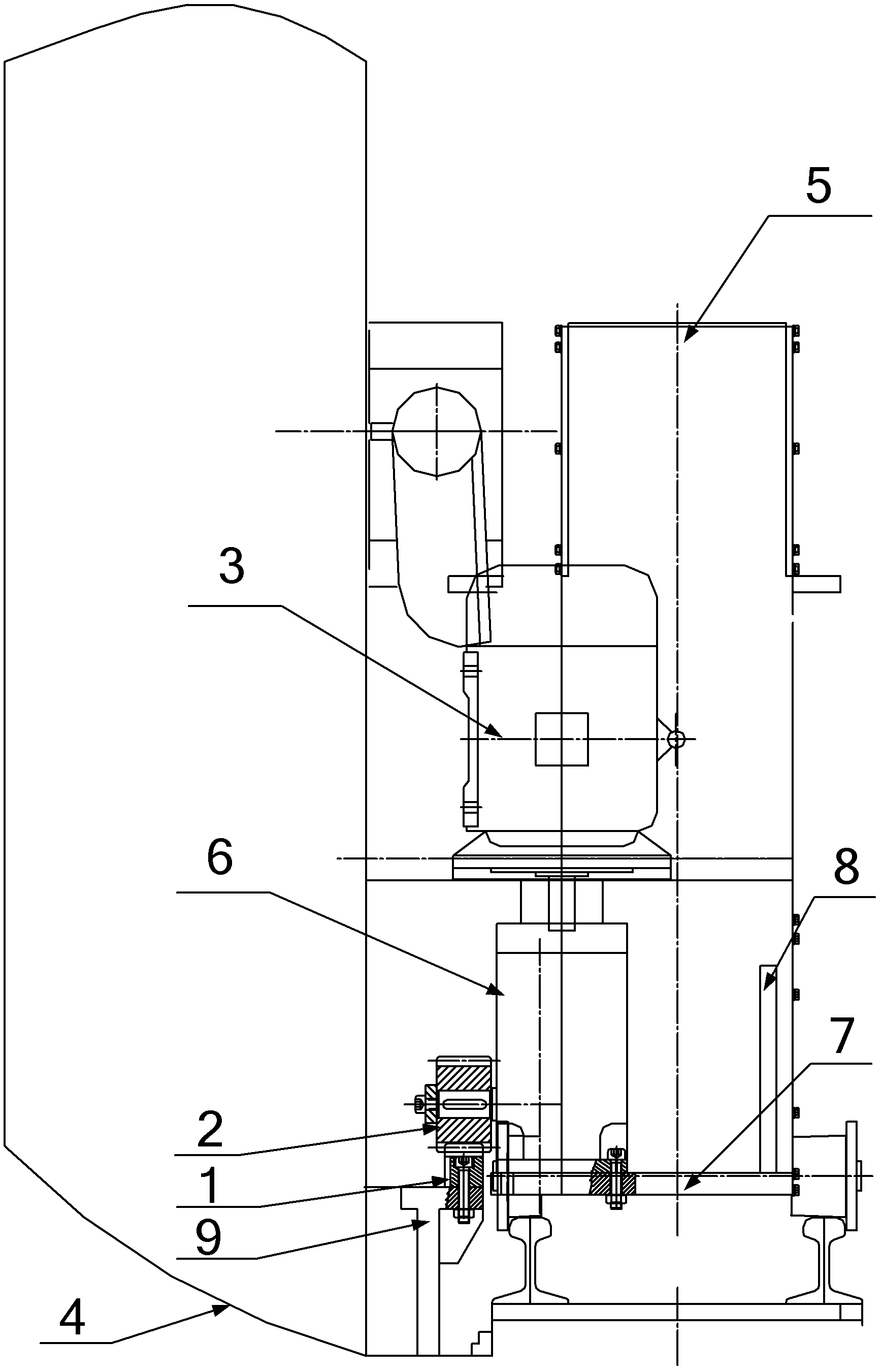
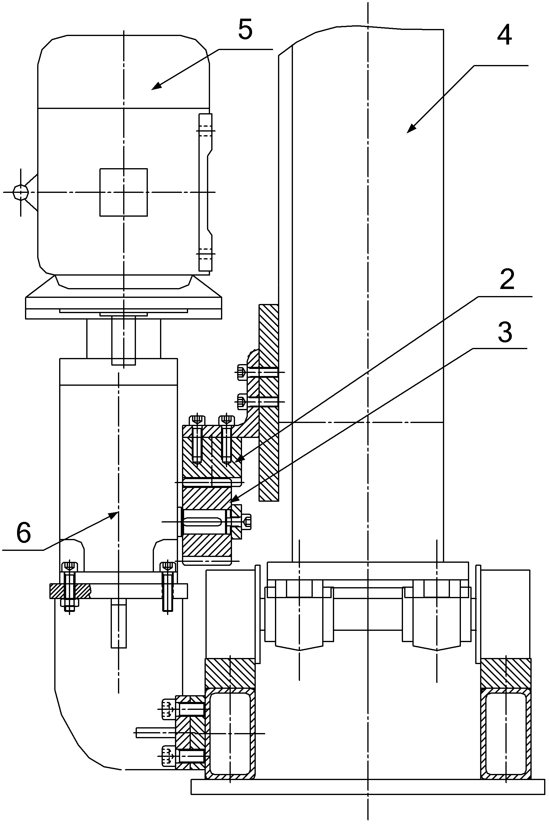
[0039] The invention discloses a rolling mill thickness gauge traveling device, which optimizes the rolling mill thickness gauge's running characteristics, ensures the rolling mill thickness gauge's walking stability, and improves the rolling mill thickness gauge's working quality.

[0040] The following will clearly and completely describe the technical solutions in the embodiments of the present invention with reference to the accompanying drawings in the embodiments of the present invention. Obviously, the described embodiments are only some, not all, embodiments of the present invention. Based on the embodiments of the present invention, all other embodiments obtained by persons of ordinary skill in the art without making creative efforts belong to the protection scope of the present invention.

[0041] see figure 1 , figure 2 and image 3 , the rolling mill thickness gauge traveling device provided by the embodiment of the present invention includes:

[0042] The rack...


PUM


Abstract

The invention discloses a running gear of a thickness gauge for a rolling mill. The running gear comprises a rack (1), a gear (2) and a running motor (3), wherein the rack (1) is arranged along the horizontal direction; the gear (2) is meshed with the rack (1); the running motor (3) is used for driving the gear (2); one of the rack (1) and the running motor (3) is fixed on a frame (4) of the rolling machine; and the other one of the rack (1) and the running motor (3) is fixed on the thickness gauge (5) for the rolling mill. In the running gear of the thickness gauge for the rolling mill, a gear rack pair structure consisting of the rack (1) and the gear (2) is used for driving, so the thickness gauge (5) for the rolling mill can run in the horizontal direction, the problem of running instability caused by the cylinder push running mode in the prior art is effectively solved, the running characteristic of the thickness gauge (5) for the rolling mill is optimized, the thickness measuring precision is improved and the product quality is improved. The invention also discloses the thickness gauge for the rolling mill, which adopts the running gear.

Description

technical field [0001] The invention relates to the technical field of rolling mills, in particular to a rolling mill thickness gauge and a traveling device thereof. Background technique [0002] Rolling mill is the equipment that realizes the metal rolling process. It generally refers to the equipment that completes the whole process of rolling material production, including main equipment, auxiliary equipment, lifting and transportation equipment, and auxiliary equipment. A thickness gauge is an instrument used to measure the thickness of an object. It is commonly used in industrial production to continuously measure the thickness of products (such as steel plates, steel strips, paper, etc.). [0003] The walking mode of the existing rolling mill thickness gauge is the driving mode driven by the cylinder. The disadvantage of the cylinder is that many factors such as the stability of the air pressure, the load situation and the walking road condition will affect the unifor...

Claims


Application Information

Patent Timeline
Patent Type & Authority Applications(China)
IPC IPC(8): B21B38/04
Inventor 戢亮慕刚毅龙再祥孔令平
Owner SOUTHWEST ALUMINUM GRP
Learn More