
Traction type rolling welding machine

A rolling welding machine and traction type technology, applied in the direction of roller electrode welding, welding equipment, resistance welding equipment, etc., can solve the problem that the pusher plate and the main plate cannot be rotated precisely synchronously, the longitudinal bars of the steel cage are twisted radially, and the twist bars And other issues

Active Publication Date: 2012-05-23
江苏邦威机械制造有限公司
View PDF7 Cites 20 Cited by
  • Summary
  • Abstract
  • Description
  • Claims
  • Application Information

AI Technical Summary

Problems solved by technology

The rib-pushing plate and the main plate are connected by a connecting cylinder to achieve synchronous rotation. However, due to manufacturing errors, the rib-pushing plate and the main plate cannot actually rotate accurately and synchronously. tendon phenomenon

Method used


Image

  • Traction type rolling welding machine
  • Traction type rolling welding machine
  • Traction type rolling welding machine

Examples


Embodiment Construction

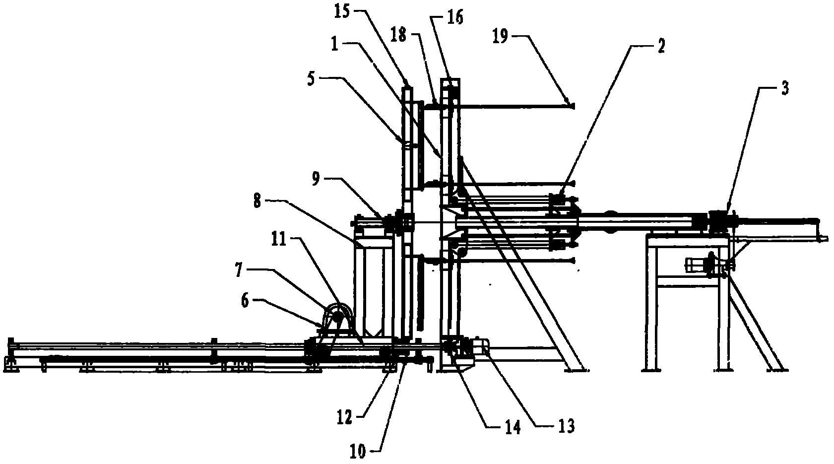
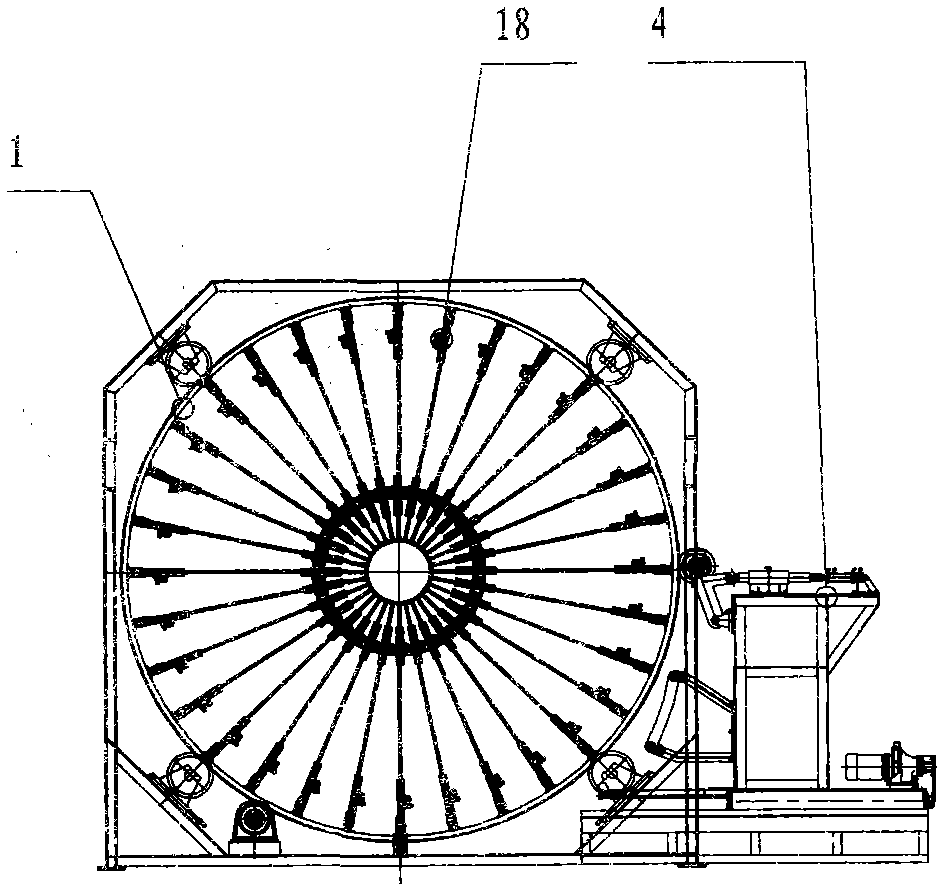
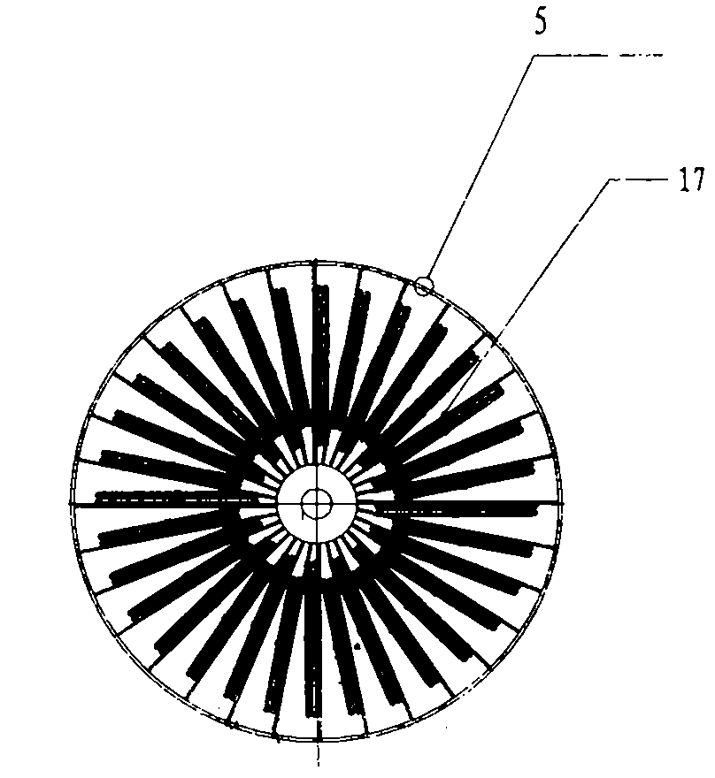
[0010] Such as figure 1 As shown, the traction type seam welding machine of the present invention includes a main plate 1 , a diameter reducing mechanism 2 of a welding table, a diameter expanding mechanism 3 , a welding mechanism 4 , a traction face plate 5 and a traction trolley 6 . The traction trolley 6 is composed of a driving mechanism 7 and a frame 8. The mandrel 9 of the traction faceplate is connected with the traction trolley frame 8. The transmission sprocket 10 of the traction faceplate 5 is set on the transmission square steel 11 and connected to the traction trolley through the bearing seat 12. Frames 8 are connected, and the traction faceplate drive sprocket is meshed with the chain on the outer circumferential surface of the traction faceplate. When the traction trolley drives the traction faceplate to move axially, the traction faceplate drive sprocket 10 slides on the transmission square steel 11 and keeps The chain 15 on the outer peripheral surface of the t...


PUM


Abstract

The invention relates to a traction type rolling welding machine, which comprises a master disc, a welding table reducing mechanism, an expanding mechanism, a welding mechanism, a traction disc chuck and a traction trolley, wherein the traction disc chuck keeps synchronous rotation with the master disc under the transmission of transmission square steel while clamping longitudinal bars of a steel reinforcement cage to make axial motion under the driving of the traction trolley. The traction disc chuck keeps synchronous rotation with the master disc under the transmission of the transmission square steel while dragging the longitudinal bars of the steel reinforcement cage to make axial motion under the driving of the traction trolley, so the bar twisting of the steel reinforcement cage can be avoided.

Description

technical field [0001] The invention relates to a concrete product production machine, in particular to a rolling welding machine for making reinforced concrete pipe reinforcement cages. Background technique [0002] At present, automatic variable diameter roll welding machines are widely used in China to make steel cages. The automatic variable-diameter roll welding machine pushes out the steel bars in the bar-piercing pipe through the bar-pushing mechanism to form longitudinal bars. The rib-pushing disc and the main disc are connected by a connecting cylinder to achieve synchronous rotation. However, due to manufacturing errors, the rib-pushing disc and the main disc cannot actually rotate accurately and synchronously. Muscle phenomenon. Contents of the invention [0003] The object of the present invention is to provide a traction type seam welding machine, which can be used to make a reinforcement cage, and the reinforcement cage will not have twisted tendons. [00...

Claims


Application Information

Patent Timeline
Patent Type & Authority Applications(China)
IPC IPC(8): B23K11/06B23K11/34B23K11/36
Inventor 孟祥建
Owner 江苏邦威机械制造有限公司
Learn More