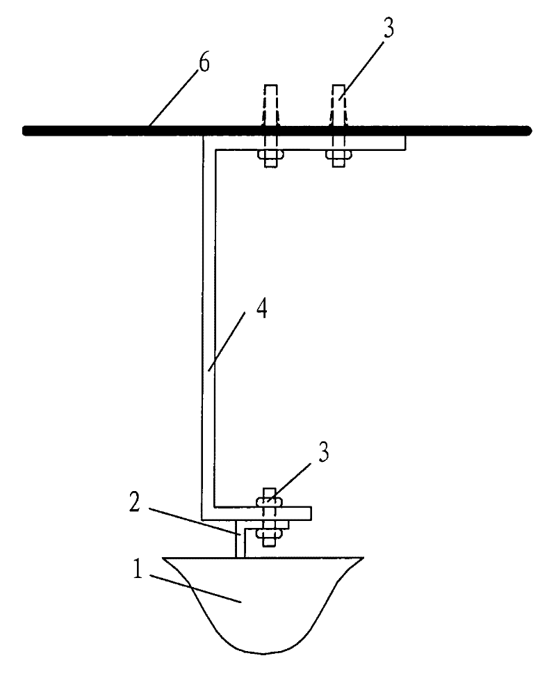
Antenna fixing device
An antenna fixing device and antenna technology, applied in the field of communication, can solve the problems of difficult antenna fixing, poor ability to adapt to the environment, and high cost, and achieve the effects of avoiding shaking, reducing costs, and simple fixing methods
- Summary
- Abstract
- Description
- Claims
- Application Information
AI Technical Summary
Problems solved by technology
Method used
Image
Examples
example 1
[0038] In this example, the manner in which the device fixes the antenna on the support plate by means of a component similar to the antenna support rod in the prior art will be described.
[0039] Figure 2a is a schematic diagram of the antenna fixing device fixing the antenna in this example; Figure 2b is along the Figure 2a Schematic diagram when viewed in the A direction.
[0040] like Figure 2a and Figure 2b As shown, in this example, the support plate 5 is rectangular and wider than the antenna 1, and there are attachments 6 fixed on both sides (in this example, the attachment 6 can be a wall, a vertical steel frame, etc. that are approximately perpendicular to the Horizontal structure), and the support plate 5 is fixed to the attachment body 6 by the bolt 3'; the antenna support rod 4 is in a concave shape, and one end of the antenna support rod 4 is fixed on the support plate 5 by the bolt 3 (located above the support plate 5) , and the other end is fixed with ...
example 2
[0043] Figure 3a is a schematic diagram of the fixed antenna of the antenna fixing device in this example; Figure 3b is along Figure 3a The schematic diagram when viewed from the A direction in .
[0044] like Figure 3a and Figure 3b As shown, the same as Example 1, the antenna fixing device of this example also includes an antenna support rod 4 , a support plate 5 , and an antenna bracket 2 . The difference is that only one end of the support plate 5 is fixed to the attachment 6 .
example 3
[0046] In this example, the antenna fixing method of directly fixing the antenna bracket to the support plate will be described.
[0047] Figure 4a is a schematic diagram of the fixed antenna of the antenna fixing device in this example; Figure 4b is along Figure 4a The schematic diagram when viewed from the A direction in .
[0048] like Figure 4a and 4b As shown, compared with examples 1 and 2, the antenna fixing device in this example omits the antenna support rod; the antenna bracket 2 is also L-shaped, with one end fixing the antenna 1 and the other end fixed on the support plate 5 by bolts 3; Both ends of the support plate 5 are respectively fixed on the attachments 6 located on both sides of the support plate 5; wherein, the radiation direction of the antenna 1 is upward, and since the antenna support rod is omitted, the distance between the antenna and the support plate 5 can be shorter, This further ensures that the antenna will not shake, and at the same tim...
PUM
 Abstract
Description
Claims
Application Information
 - R&D Engineer
- R&D Manager
- IP Professional
- Industry Leading Data Capabilities
- Powerful AI technology
- Patent DNA Extraction
Browse by: Latest US Patents, China's latest patents, Technical Efficacy Thesaurus, Application Domain, Technology Topic, Popular Technical Reports.
© 2024 PatSnap. All rights reserved.Legal|Privacy policy|Modern Slavery Act Transparency Statement|Sitemap|About US| Contact US: help@patsnap.com


