Method for recycling optical devices

An optical device and isolator technology, applied in the coupling of optical waveguides and other directions, can solve problems such as unfavorable enterprises to save costs, waste of optical components, and devices that can no longer be used, and achieve the effect of saving materials, prolonging service life, and saving expenses

Inactive Publication Date: 2012-05-02
SOURCE PHOTONICS CHENGDU
View PDF0 Cites 0 Cited by
  • Summary
  • Abstract
  • Description
  • Claims
  • Application Information

AI Technical Summary

Problems solved by technology

[0003] However, in the prior art, there is no specific method for recycling each optical device. Usually, when other parts of the entire device that only use the optical device are damaged or cannot be used for other reasons, the entire device cannot be used anymore. , which leads to a lot of waste of optical components and a lot of material waste, which is not conducive to the cost saving of enterprises

Method used


Image

  • Method for recycling optical devices
  • Method for recycling optical devices
  • Method for recycling optical devices

Examples


Embodiment Construction

[0018] The following will clearly and completely describe the technical solutions in the embodiments of the present invention with reference to the accompanying drawings in the embodiments of the present invention. Obviously, the described embodiments are only some, not all, embodiments of the present invention. Based on the embodiments of the present invention, all other embodiments obtained by persons of ordinary skill in the art without creative efforts fall within the protection scope of the present invention.

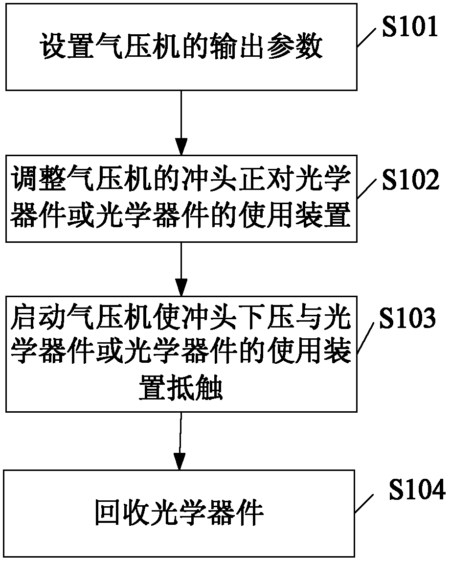
[0019] figure 1 Demonstrated the main step process of the present invention recycling optical device, as figure 1 As shown, the method for recovering the optical device includes the following steps: setting the output parameters of the air press (step S101); adjusting the punch of the air press to face the optical device or the device for using the optical device (step S102); starting the air press to use Pressing down the punch interferes with the optical device ...


PUM


Abstract

The invention discloses a method for recycling optical devices. The optical devices comprise tail fibers, inserted cores and isolators. The method comprises the following steps: setting the output parameters of a gas compressor; adjusting a punch of the gas compressor to be over against the optical devices or using devices of the optical devices; starting the gas compressor to press the punch downwards so as to ensure the punch to abut against the optical devices or the using devices of the optical devices; and recycling the optical devices. The method has the following beneficial effects: the optical devices can be effectively separated and recycled; the service lives of the optical devices are prolonged; the materials are saved and the expenditures are saved for the enterprises; and the recycling quality of the optical devices is ensured.

Description

technical field [0001] The invention relates to the field of industrial recycling, in particular to a method for recycling optical devices. Background technique [0002] Optical devices are mainly used to adjust and change the transmission of various lights or optical signals, so that the transmission of light or optical signals can be carried out according to the preset requirements in order to achieve the expected purpose. For example, the optical device ferrule is usually installed in various lasers, and its main function is to couple the light emitted by the laser to the inside of the fiber for low-loss transmission or to connect the external light to the photodiode at the light-receiving end with low loss. Transmission; optical device isolator is a non-reciprocal device, its main function is to only allow light waves to transmit in one direction, and prevent light waves from transmitting in other directions, especially in the opposite direction, and isolators are usuall...

Claims


Application Information

Patent Timeline
Patent Type & Authority Applications(China)
IPC IPC(8): G02B6/36G02B6/38
Inventor 田英俊杨帅
Owner SOURCE PHOTONICS CHENGDU
Why Eureka
Try Eureka