Guide plate

一种导向板、导向链的技术,应用在导向板领域,能够解决增加发热及噪音、偏磨损、不能完全防止弓状变形导向板弓状弯曲等问题,达到抑制弓状变形、防止弓状变形的效果

Inactive Publication Date: 2012-05-02
TSUBAKIMOTO CHAIN CO
View PDF5 Cites 1 Cited by
  • Summary
  • Abstract
  • Description
  • Claims
  • Application Information

AI Technical Summary

Problems solved by technology

[0013] However, in the known guide plates described in Patent Document 1, etc., under no-load conditions, the two outermost surfaces of the front and rear pair of guide pin holes are arranged on the two outermost surfaces of the front and rear pair of connecting pin holes of the intermediate link plate. The two outermost surfaces are at the same position, therefore, under the load state of applying tension to the chain, along with the deformation of the guide plate, a slight stress in the bending direction still occurs on the connecting pin, so that the length of the connecting pin cannot be completely prevented. Bowing of the locking pin and bowing of the guide plate
[0014] In addition, due to the deformation of the guide plate, the angles of the two outermost faces of the front and rear pair of guide pin holes change, so the two outermost faces of the front and rear pair of connecting pin holes of the middle link plate are in the width direction. The upper shape is inconsistent, and the long lock pin used as the connecting pin is in partial contact with the front and rear pair of connecting pin holes of the middle link plate, resulting in partial wear and partial load, resulting in problems of increased heat and noise

Method used


Image

  • Guide plate
  • Guide plate
  • Guide plate

Examples


Embodiment 1

[0049] Hereinafter, the guide plate in the Example of this invention is demonstrated based on drawing.

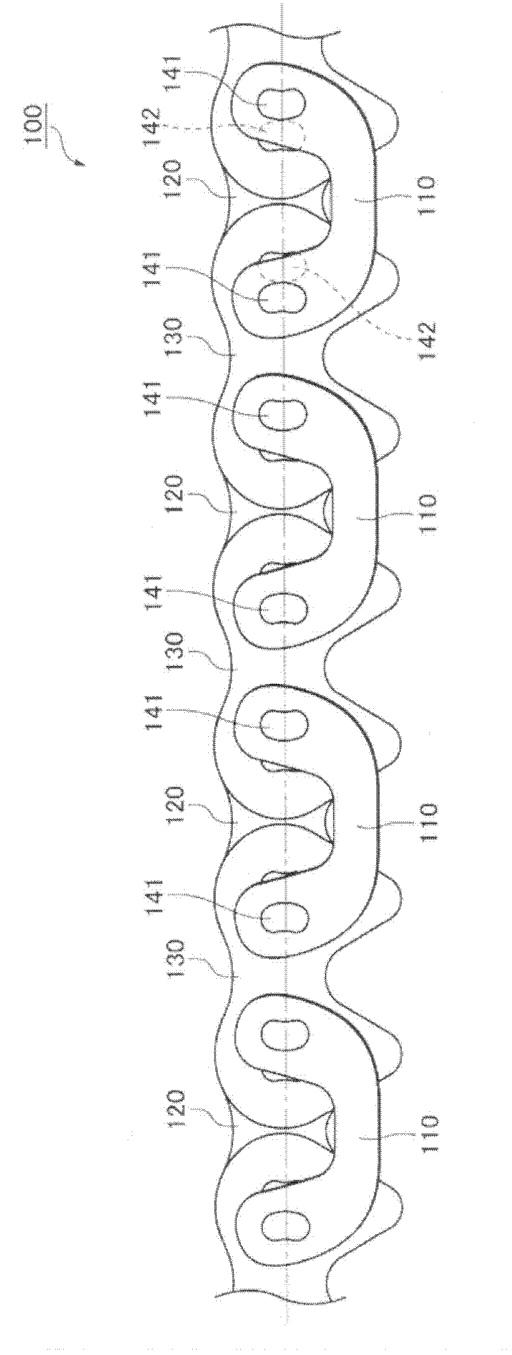
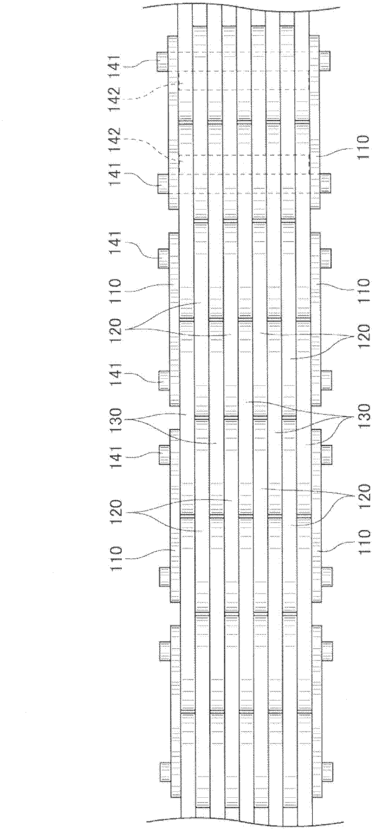
[0050] Such as figure 1 , figure 2 As shown, the silent chain 100 that adopts the guide plate 110 of an embodiment of the present invention has the following structure: each of the guide chain link rows has a pair of teeth and the middle link plate 120 of the connecting pin hole and the non-guide chain link row. The inner chain plates 130 are stacked alternately, and at the same time, a pair of long locking pins 141 and short locking pins 142 with long and short lock faces are provided, so that the locking faces are opposed to the connecting pin holes of the middle chain plates 120 and the inner chain plates 130, The intermediate link plates 120 and the inner link plates 130 are rotatably connected by being inserted into the connecting pin holes. Furthermore, the guide plates 110 are disposed on the outermost sides of the intermediate link plates 120 of the guide link ro...


PUM


Abstract

In a silent chain, guide plates are U-shaped so that they can deform when tension is applied to the chain, thereby avoiding deformation of the connecting pins of the chain and warping of the guide plates (110). When the chain is unloaded, the frontmost edges of front pin holes of intermediate link plates of each link row are located forward of the frontmost edges of the front pin holes of the guide plates of the same link row, and the rearmost edges of the rear pin holes of the intermediate link plates (113) of each link row are located rearward of the rearmost edges of the rear pin holes of the guide plates of the same link row.

Description

technical field [0001] The invention relates to a guide plate disposed on the outermost side of a chain formed by alternately connecting a plurality of link plates through connecting pins. Background technique [0002] Conventionally, there is known a silent chain used as a transmission chain. The silent chain has a guide link row consisting of a pair of guide plates and a plurality of intermediate link plates arranged between the guide plates, and a plurality of inner chain links. A non-guiding chain link column composed of plates; a long and a short pair of long and short locking pins with locking faces as connecting pins, so that the locking face opposes the front and rear pair of connecting pins of the intermediate and inner chain plates hole, thus inserted into the connecting pin hole, and the long lock pin fits in the front and rear pair of guide pin holes of the guide plate arranged on the two outer sides in the width direction of the guide chain link row, so that the...

Claims


Application Information

Patent Timeline
Patent Type & Authority Applications(China)
IPC IPC(8): F16G13/04F16G15/12
CPCF16G13/04
Inventor 平井晶
Owner TSUBAKIMOTO CHAIN CO
Why Eureka
Try Eureka