Construction method of equipment base pre-reservation anchor bolt square hole

An equipment foundation and anchor bolt technology is applied in the construction field of reserved square holes for equipment foundation, which can solve the problems of difficulty in applying force, inability to meet the needs of large upper and lower openings, and inconvenient dismantling, so as to improve the pull-out bearing capacity and reduce the The effect of labor intensity and construction cost reduction

Active Publication Date: 2013-12-11
CHINA FIRST METALLURGICAL GROUP
View PDF3 Cites 0 Cited by
  • Summary
  • Abstract
  • Description
  • Claims
  • Application Information

AI Technical Summary

Problems solved by technology

The steel corrugated pipe adopts a tool with a slot at one end and a handle at the other end. The slot is clamped to the steel bellows, and the steel corrugated pipe is peeled off layer by layer. The removal effect is not satisfactory; the plastic pipe is baked at high temperature to make it soft, and then Pulling out as a whole, the method sometimes causes the plastic pipe to break off, which directly affects the strength of the secondary grouting of the anchor bolt holes; the wooden formwork adopts a square pyramid-shaped wooden box structure with a large upper opening and a smaller lower opening, with small cross-section and deep depth. For deep holes, there will be various difficulties such as difficulty in force and limited space when dismantling
In order to improve the pull-out bearing capacity of bolts, a structure with the lower opening slightly larger than the upper opening is often used. Steel bellows and plastic pipes are standard materials for pipe diameters, which cannot meet the requirements of large upper openings and smaller lower openings. The upper opening is smaller than the lower opening. The large pyramid-shaped wooden box cannot be dismantled even if it meets the size requirements
Namely: the anchor bolt hole is characterized by a long and narrow space with a large aspect ratio, so it brings great inconvenience to the demolition, and its formwork cannot be reused during the demolition process

Method used


Image

  • Construction method of equipment base pre-reservation anchor bolt square hole
  • Construction method of equipment base pre-reservation anchor bolt square hole
  • Construction method of equipment base pre-reservation anchor bolt square hole

Examples


Embodiment Construction

[0024] In order to better understand the present invention, the technical solutions of the present invention will be further described below in conjunction with the embodiments and the accompanying drawings.

[0025] The construction method of reserving square holes for anchor bolts in the equipment foundation includes the following steps:

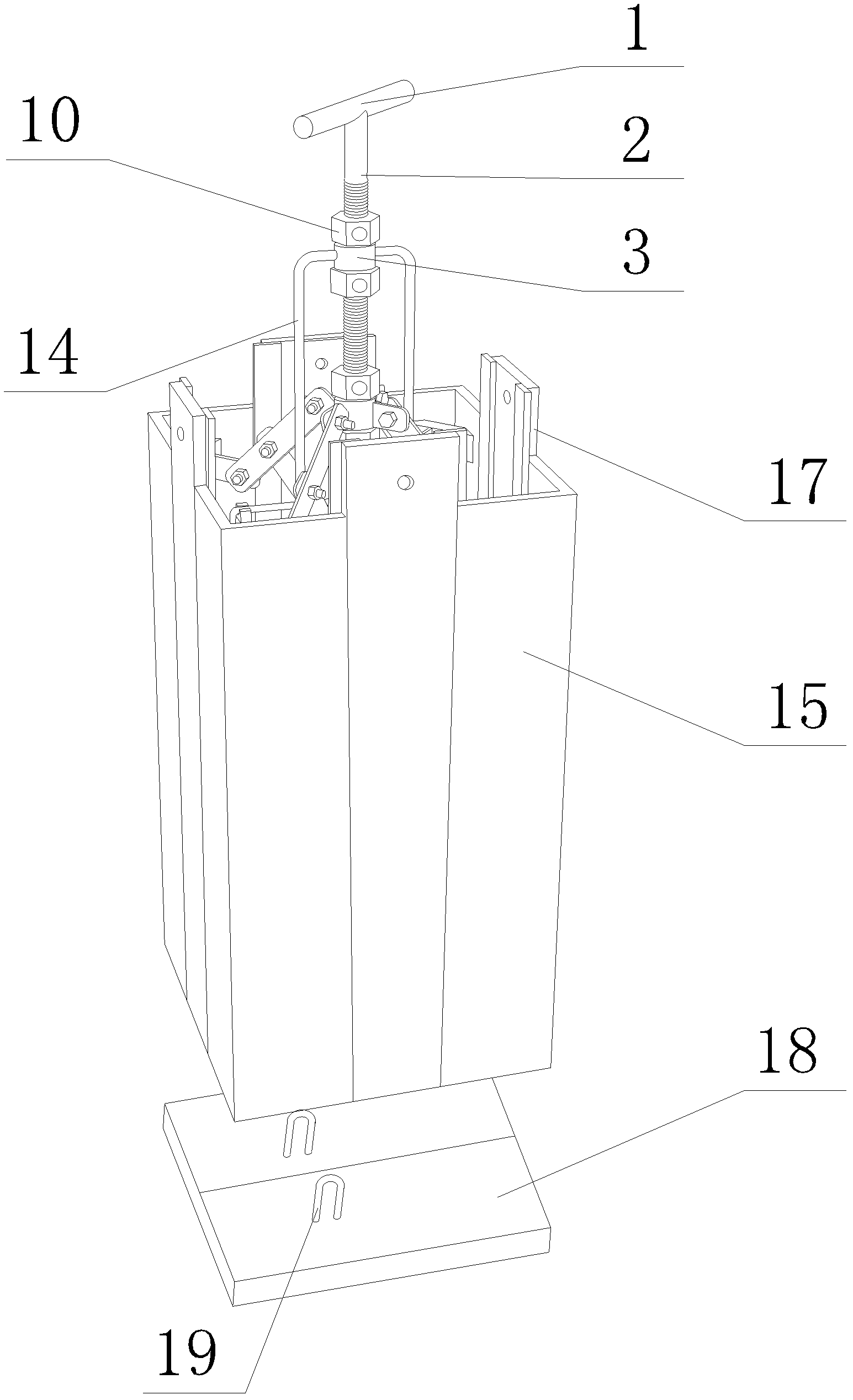
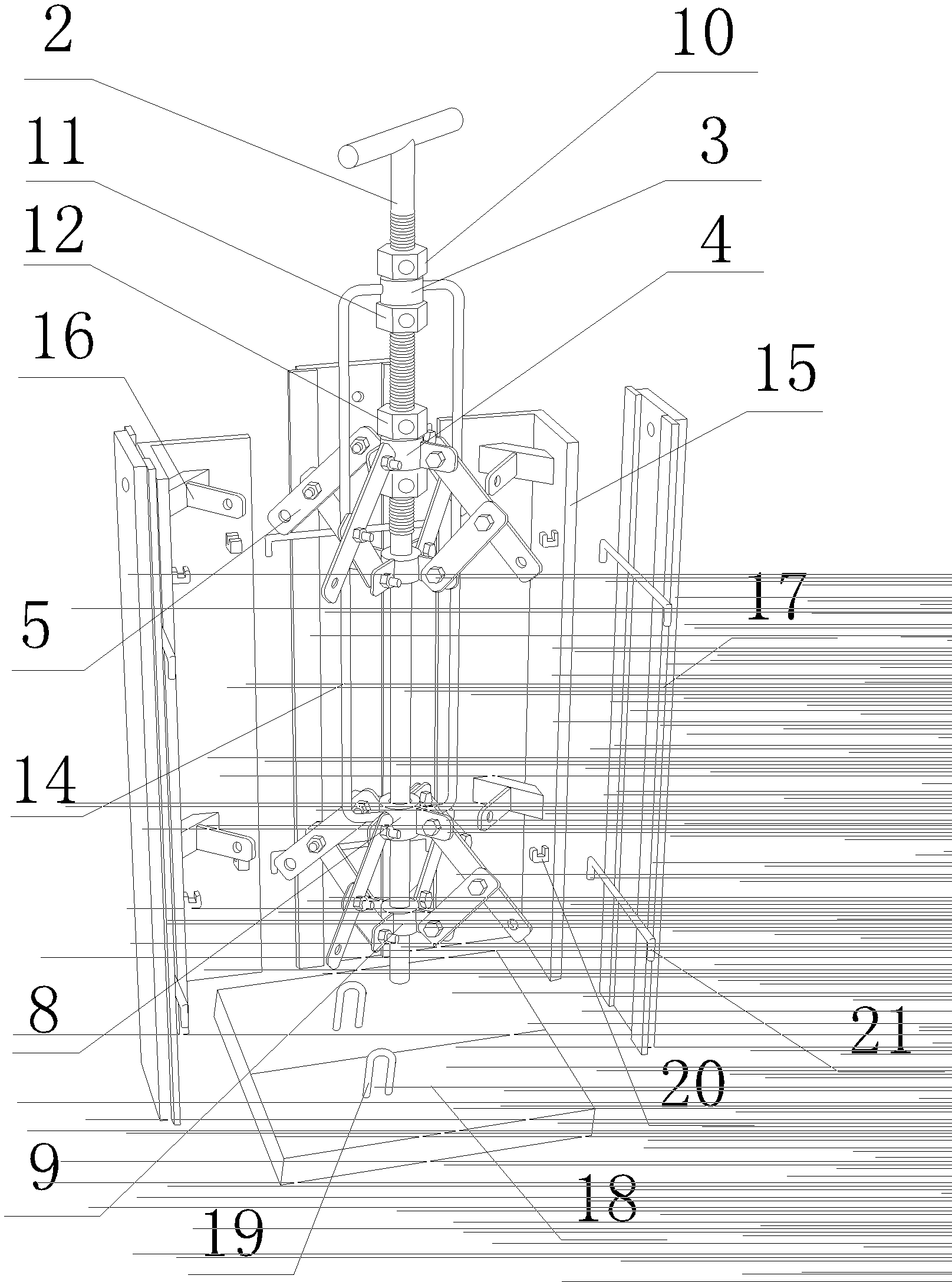
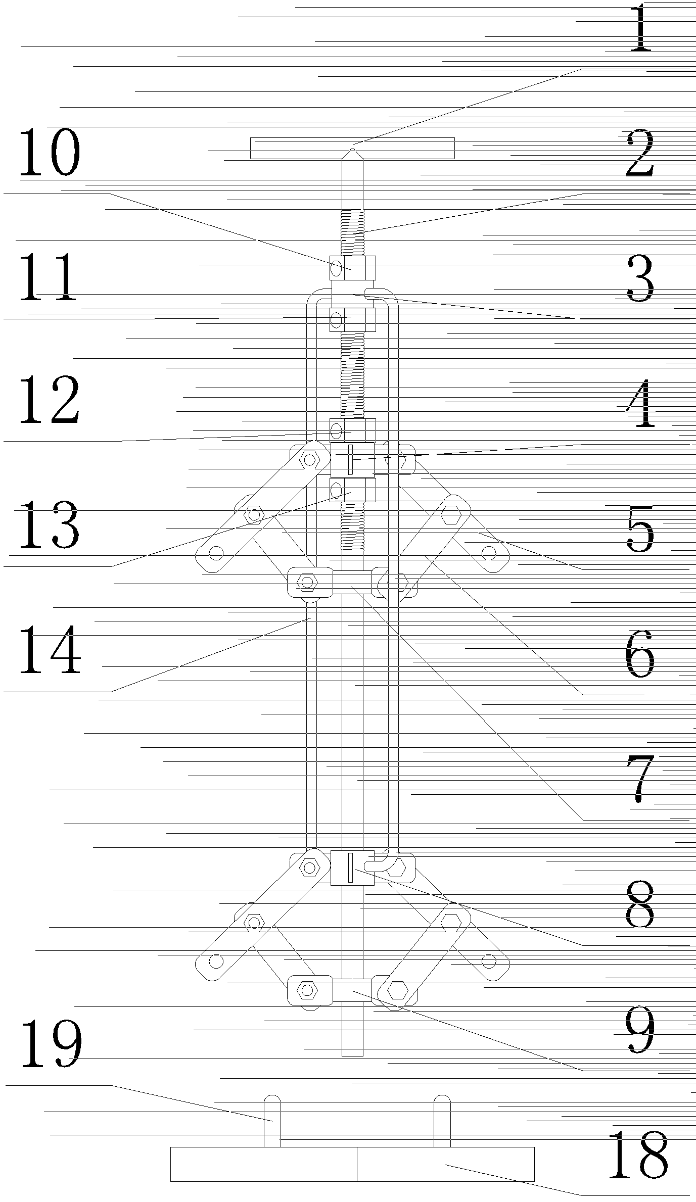
[0026] The first step is to assemble the mold: a reusable mold with square holes reserved for the equipment foundation (that is, square holes for anchor bolts), its structure is as follows Figure 1 to Figure 3 As shown, it includes a central axis 2, a first expansion and contraction device, a second expansion and contraction device, 4 corner templates 15, and 4 middle templates 17; 4 corner templates 15 are L-shaped at right angles, 4 The three corner templates 15 are distributed at the four corners, the middle template 17 is inserted between the corner templates on the same side and the corner templates, and the four corner templates 15 ...


PUM


Abstract

The invention relates to a construction method of an equipment base pre-reservation square hole, in particular to a construction method of an equipment base pre-reservation anchor bolt square hole, which is characterized by comprising the following steps that, firstly, a die is assembled; secondly, the die is erected: the size of an upper hole of the die of the equipment base pre-reservation square hole, which can be repeatedly used, is regulated according to a drawing, a fourth locating nut is unscrewed, a second sliding regulation seat moves downwards so that the rectangular size of the upper hole of an angle template is reached, a second locating nut is unscrewed, a first sliding regulation seat moves downwards so that the rectangular size of a lower hole of the angle template is reached, the third locating nut and a first locating nut are screwed, and a plastic film or an adhesive tape wraps on the outer walls of the angle template and a middle template as a protective layer; thirdly, concrete is poured; fourthly, the template is disassembled, the angle template is extracted, a wood bottom plate is lifted out, and a square hole is left; and fifthly, the hole is cleaned, and the equipment base pre-reservation anchor bolt square hole is acquired. The construction method has the advantages that the operation is simple, die stripping is rapid, and the die can be repeatedly used.

Description

technical field [0001] The invention belongs to a construction method for reserved square holes (reserved square holes for anchor bolts) in equipment foundations. Background technique [0002] In the construction of the equipment foundation, the foundation bolt holes of the equipment need to be reserved on the concrete foundation. The reserved method generally adopts the methods of supporting steel bellows, plastic pipes or supporting wooden formwork, etc., and removes them in time after the concrete solidifies. The steel corrugated pipe adopts a tool with a slot at one end and a handle at the other end. The slot is clamped to the steel bellows, and the steel corrugated pipe is peeled off layer by layer. The removal effect is not satisfactory; the plastic pipe is baked at high temperature to make it soft, and then Pulling out as a whole, the method sometimes causes the plastic pipe to break off, which directly affects the strength of the secondary grouting of the anchor bolt...

Claims


Application Information

Patent Timeline
Patent Type & Authority Patents(China)
IPC IPC(8): E04G21/00E04G15/04
Inventor 王平夏春
Owner CHINA FIRST METALLURGICAL GROUP
Why Eureka
Try Eureka