
Truck for removing sludge from inspection well

A technology for silt and manholes, which is applied in waterway systems, water supply devices, buildings, etc., can solve the problems of short continuous operation time, cumbersome operation, and difficulty in unloading.

Inactive Publication Date: 2012-05-02
宋兰芳 +2
View PDF0 Cites 10 Cited by
  • Summary
  • Abstract
  • Description
  • Claims
  • Application Information

AI Technical Summary

Problems solved by technology

Moreover, the silt in the mud storage tank will settle at the bottom of the mud storage tank after being bumped during transportation, making it difficult to unload.
For this reason, the current urban inspection well removal operation has short continuous operation time, low benefit, high cost, and cumbersome operations.

Method used


Image

  • Truck for removing sludge from inspection well
  • Truck for removing sludge from inspection well
  • Truck for removing sludge from inspection well

Examples


Embodiment Construction

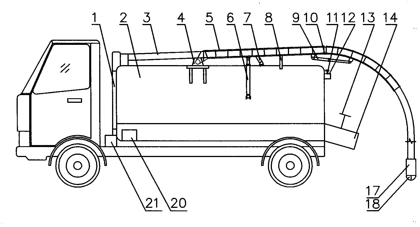
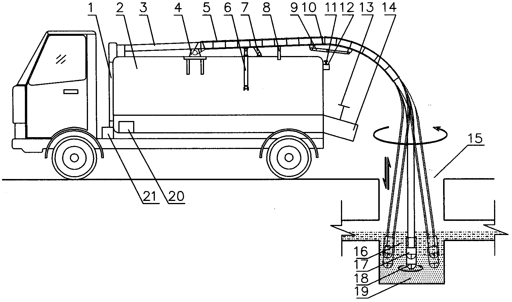
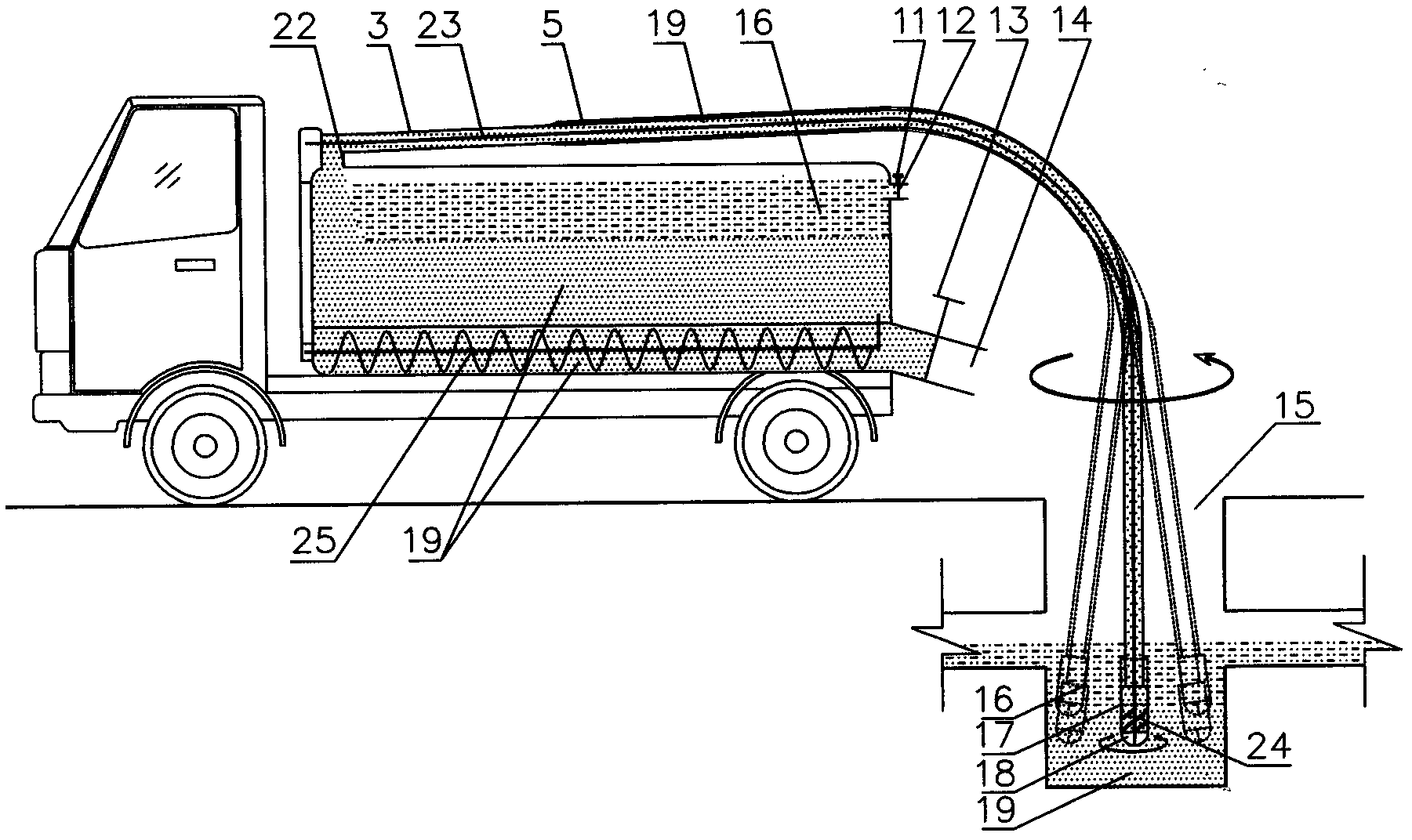
[0011] Such as figure 1 , figure 2 , image 3 , Figure 4 As shown, by 20 microcomputer controllers, start the vehicle power, and connect the vehicle power unit through 1, open 21 oil pumps and 23 drive flexible shafts. At the same time, 20 microcomputer controllers drive 6 mud hoses to move up and down, 7 mud hoses to move left and right, 9 mud hoses to move back and forth, and 3 mud hoses and 5 mud hose supports to move from 8 The mud hose bracket shelf is removed. 23 flexible shafts, 3 mud hoses, 17 mud pumps, and 18 mixing heads are correctly sent into the 15 inspection wells. According to the size of 15 inspection wells, select the program that 20 microcomputer controllers have set. Under the control of the program, in a spiral form from top to bottom, use 18 stirring heads to stir the 19 sludge deposited in 15 inspection wells to make it flow. Mud hose and 22 mud storage tanks enter the mud inlet, input in 2 mud storage tanks. After continuous operation and 19 si...


PUM


Abstract

The invention relates to a truck for removing sludge from an inspection well, which belongs to the technique of mechanically removing the sludge from the inspection well for the urban pipe network. When the sludge in the inspection well is removed, an inspection well cover is opened. The truck power is started by a microcontroller to start an oil pump and drive a soft shaft. Meanwhile, a sludge conveying flexible pipe is driven to move an oil cylinder upwards, downwards, leftwards, rightwards, frontwards and backwards, and the soft shaft, the sludge conveying flexible pipe, a sludge pump and a stirring head are correctly conveyed in the inspection well. According to size of the inspection well, a program that has been set by the microcomputer controller is selected. Under the control of the program, the sludge deposited in the inspection well is stirred in a flowing shape by the stirring head spirally from top down, and the sludge in the flowing shape is conveyed into a sludge storage tank by effect of an impeller of the sludge pump. The waste water in the sludge storage tank is discharged through a waste water outlet after continuous operation and sludge deposition, so that the sludge storage tank can store the sludge maximally. After the sludge is stored in the whole sludge storage tank, the sludge storage tank is conveyed to a named place where the sludge is discharged. Finally the sludge deposited on the bottom of the sludge storage tank is pushed out from a sludge discharge outlet by a sludge discharge spiral rod.

Description

technical field [0001] The invention relates to a mechanized technology for removing sludge from inspection wells in urban pipe networks, in particular to a vehicle for removing sludge from inspection wells. Background technique [0002] At present, most of the silt removal operations in urban manholes are still dug manually, which is labor-intensive and unsafe. Because there are various toxic gases in the inspection well, workers will be poisoned if they do not operate properly. If the cleared silt cannot be transported away in time, it will emit a foul smell and cause secondary pollution to the urban environment. The mechanically operated vacuum suction truck cannot suck out the sludge deposited at the bottom of the inspection well. Even if it is washed with a high-pressure water gun, the operation is cumbersome, the labor intensity is high, and the efficiency is low. After being washed by the high-pressure water gun, most of the waste water sucked by the vacuum suction...

Claims


Application Information

Patent Timeline
Patent Type & Authority Applications(China)
IPC IPC(8): E03F7/10
Inventor 宋兰芳陆金娥宋健
Owner 宋兰芳
Learn More