Polarization voltage detection circuit used in electromagnetic flow meter
A technology of electromagnetic flowmeter and polarization voltage, which is used in the measurement of current/voltage, measurement of electrical variables, and direction of current indication. and other problems, to achieve the effect of correct measurement, simple circuit, economical and practical
- Summary
- Abstract
- Description
- Claims
- Application Information
AI Technical Summary
Problems solved by technology
Method used
Image
Examples
Embodiment Construction
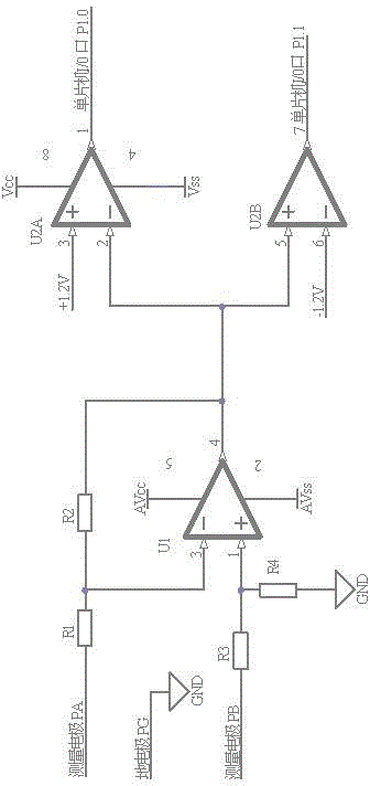
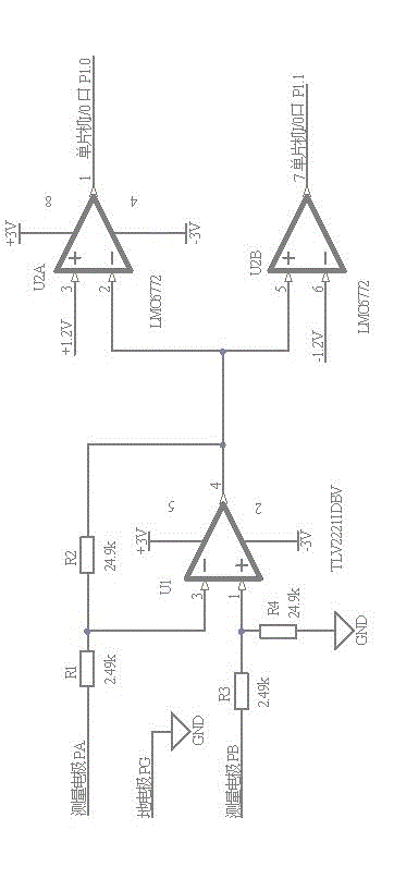
[0008] Such as figure 1 As shown, a circuit applied to the detection of the polarization voltage of the electromagnetic flowmeter, the measuring electrode PA is connected to one end of the resistor R1, the other end of the resistor R1 is connected to one end of the resistor R2, and the inverting input terminal 3 of the operational amplifier U1. The other end of resistor R2 is connected to pin 4 of the output terminal of the operational amplifier U1, pin 2 of the inverting input terminal of dual comparator channel 1 U2A, and pin 5 of the non-inverting input terminal of dual comparator channel 2 U2B, and the measuring electrode PB is connected to the resistor One end of R3 is connected, the other end of resistor R3 is connected with one end of resistor R4 and the non-inverting input terminal 1 of operational amplifier U1, the other end of resistor R4 is connected with ground, the ground electrode PG is connected with ground, and the power supply terminal of operational amplifier ...
PUM
 Abstract
Description
Claims
Application Information
 - R&D
- Intellectual Property
- Life Sciences
- Materials
- Tech Scout
- Unparalleled Data Quality
- Higher Quality Content
- 60% Fewer Hallucinations
Browse by: Latest US Patents, China's latest patents, Technical Efficacy Thesaurus, Application Domain, Technology Topic, Popular Technical Reports.
© 2025 PatSnap. All rights reserved.Legal|Privacy policy|Modern Slavery Act Transparency Statement|Sitemap|About US| Contact US: help@patsnap.com


