Tool wagon for assembling and disassembling chuck of coiler

A technology of tool trolley and winding machine, which is applied in the field of winding machine chuck disassembly and assembly tool trolley, which can solve the problems of low work efficiency, unsafety, and injury to operators, and achieve the effect of simple operation and high efficiency

Inactive Publication Date: 2012-04-18
JIANGSU SHENGHONG CHEM FIBRE CO LTD
View PDF5 Cites 3 Cited by
  • Summary
  • Abstract
  • Description
  • Claims
  • Application Information

AI Technical Summary

Problems solved by technology

[0003] Disassemble the chuck shaft from the turntable, put it on the operating platform and disassemble it, clean up the dirt and maintain it. Since the chuck shaft is very heavy, it is laborious to rotate the chuck shaft continuously during the disassembly process, and it is easy to not pay attention Rolling the chuck shaft under the operating table, injuring the operator
Therefore, when cleaning the dirt and maintaining the chuck shaft, basically two employees cooperate to complete the work, which is laborious, unsafe, and work efficiency is also very low

Method used


Image

  • Tool wagon for assembling and disassembling chuck of coiler
  • Tool wagon for assembling and disassembling chuck of coiler
  • Tool wagon for assembling and disassembling chuck of coiler

Examples


Embodiment 1

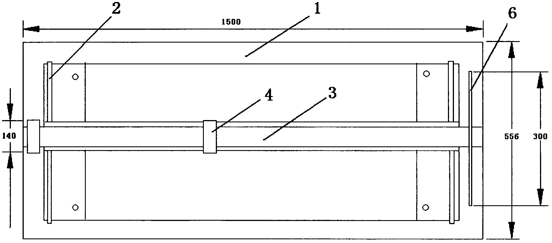
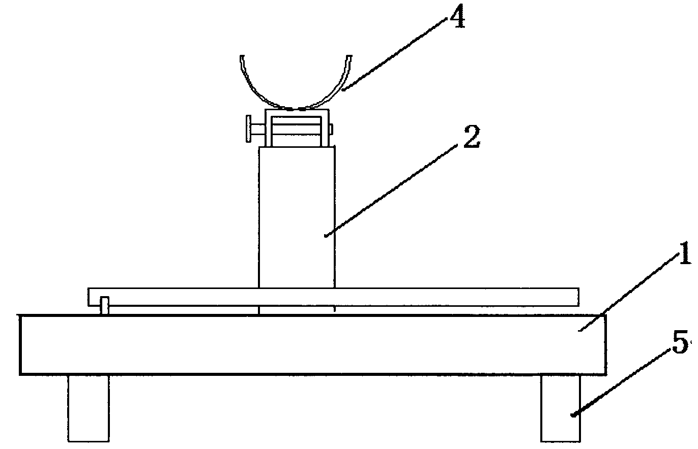
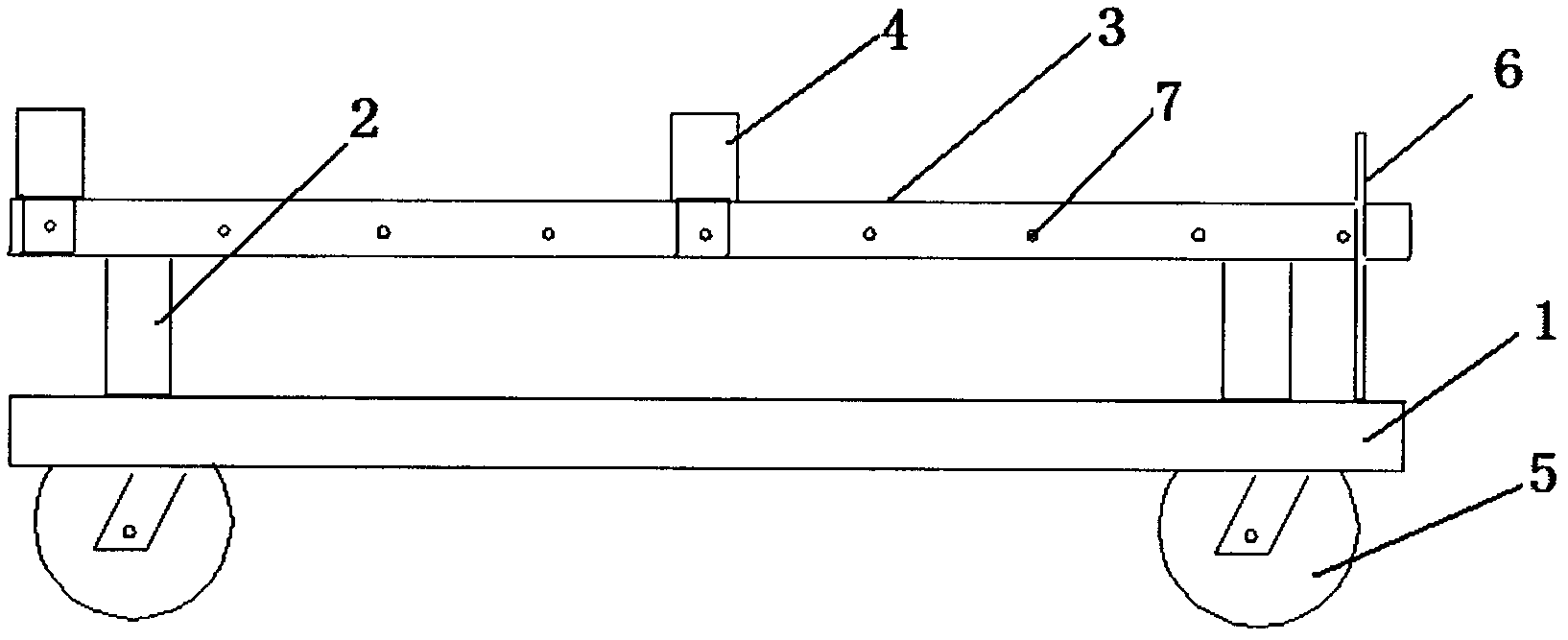
[0020] After a period of operation, the chuck of the ACW4T-1500 / 10 winding machine needs to be cleaned and maintained. Push the tool trolley of the present invention to the maintenance room using the handle 6, put it next to the winding machine, and adjust the height of the cross bar 3 through the hydraulic jack 2, so that the operator can easily disassemble the chuck for cleaning and maintenance. After determining the height, adjust The support groove on the crossbar. The crossbar is a U-shaped channel steel with a width of 65mm and a length of 1500mm. There are 9 screw holes with a diameter of 10mm evenly distributed on it. The center of the first screw hole is 80mm from the top and 15mm from the upper surface of the crossbar. , the distance between the second screw hole and the first screw hole is 165mm, and the distances between the second, third, fourth, fifth, sixth, seventh, eighth and ninth are all It is 165mm. The support groove is composed of a U-shaped channel steel...

Embodiment 2

[0022] After a period of operation, the chuck of the ACW5T-1380 / 12 winding machine needs to be cleaned and maintained. Push the tool trolley of the present invention to the maintenance room using the handle 6, put it next to the winding machine, and adjust the height of the cross bar 3 through the hydraulic jack 2, so that the operator can easily disassemble the chuck for cleaning and maintenance. After determining the height, adjust The support groove on the crossbar. The crossbar is a U-shaped channel steel with a width of 65mm and a length of 1500mm. There are 9 screw holes with a diameter of 10mm evenly distributed on it. The center of the first screw hole is 80mm from the top and 15mm from the upper surface of the crossbar. , the distance between the second screw hole and the first screw hole is 165mm, and the distances between the second, third, fourth, fifth, sixth, seventh, eighth and ninth are all It is 165mm. The support groove is composed of a U-shaped channel steel...


PUM


Abstract

The invention relates to a tool wagon for assembling and disassembling a chuck of a coiler. The tool wagon is characterized by consisting of wheels, a base, hydraulic jacks, a cross rod, support grooves and a handle, wherein the four wheels are arranged on the lower side of the base and are used for moving the tool wagon; left and right sides of the base are provided with a hydraulic jack respectively; the cross rod is supported on the jacks; and the two support grooves are formed on the cross rod and are used for placing chuck shafts. When maintained, the tool wagon can be completely cleaned without the rotation of the chuck, so operators can be prevented from being injured and the chuck can also be prevented from being damaged by two rolled-down chuck shafts. The tool wagon is easy and convenient to operate, labor-saving, safe and efficient and is suitable for ACW4T-1500 / 10, ACW5T-1380 / 12, I-Q00N6B-1200 / 20 coilers.

Description

technical field [0001] The invention relates to a tool for disassembling and assembling chemical fiber production equipment, in particular to a tool cart for disassembling and assembling chucks of winding machines. Background technique [0002] The turntable of the automatic spinning winding machine is mainly composed of a rotating disk, 2 chuck shafts, telescopic protrusions and a push-out device. Through program setting, when the winding weight set by the process is reached, the rotating disk will rotate and the paper will be loaded. The empty chuck shaft of the tube replaces the full-rolled silk cake, the frequency converter controls the speed of the synchronous motor, the protrusion on the full-rolled chuck shaft retracts, and the pushing device pushes the silk cake out, then installs the paper tube, and puts the paper tube on the chuck shaft. The protrusions of the paper tube are extended to fix the paper tube, which is used for spare. During the normal production proc...

Claims


Application Information

Patent Timeline
Patent Type & Authority Applications(China)
IPC IPC(8): B25B27/00B25H5/00
Inventor 李保磊刘峰陈丁玲辛忠凯
Owner JIANGSU SHENGHONG CHEM FIBRE CO LTD
Why Eureka
Try Eureka