Hair comb capable of removing hooked hair

A hair and crochet technology, applied in the field of hair combs, can solve the problems of high height of hair combs, inability to achieve miniaturization, etc.

Inactive Publication Date: 2012-04-18
王火标
View PDF5 Cites 13 Cited by
  • Summary
  • Abstract
  • Description
  • Claims
  • Application Information

AI Technical Summary

Problems solved by technology

[0003] Although this hair comb can achieve the purpose of removing hair, because the base plate 102, the top plate 101, the guide part 103, and the control member 4 are arranged along the same axial direction, the overall height of the hair comb is relatively large. , can not achieve the purpose of miniaturization

Method used


Image

  • Hair comb capable of removing hooked hair
  • Hair comb capable of removing hooked hair
  • Hair comb capable of removing hooked hair

Examples


Embodiment Construction

[0024] The present invention will be described in detail below in conjunction with the accompanying drawings and embodiments.

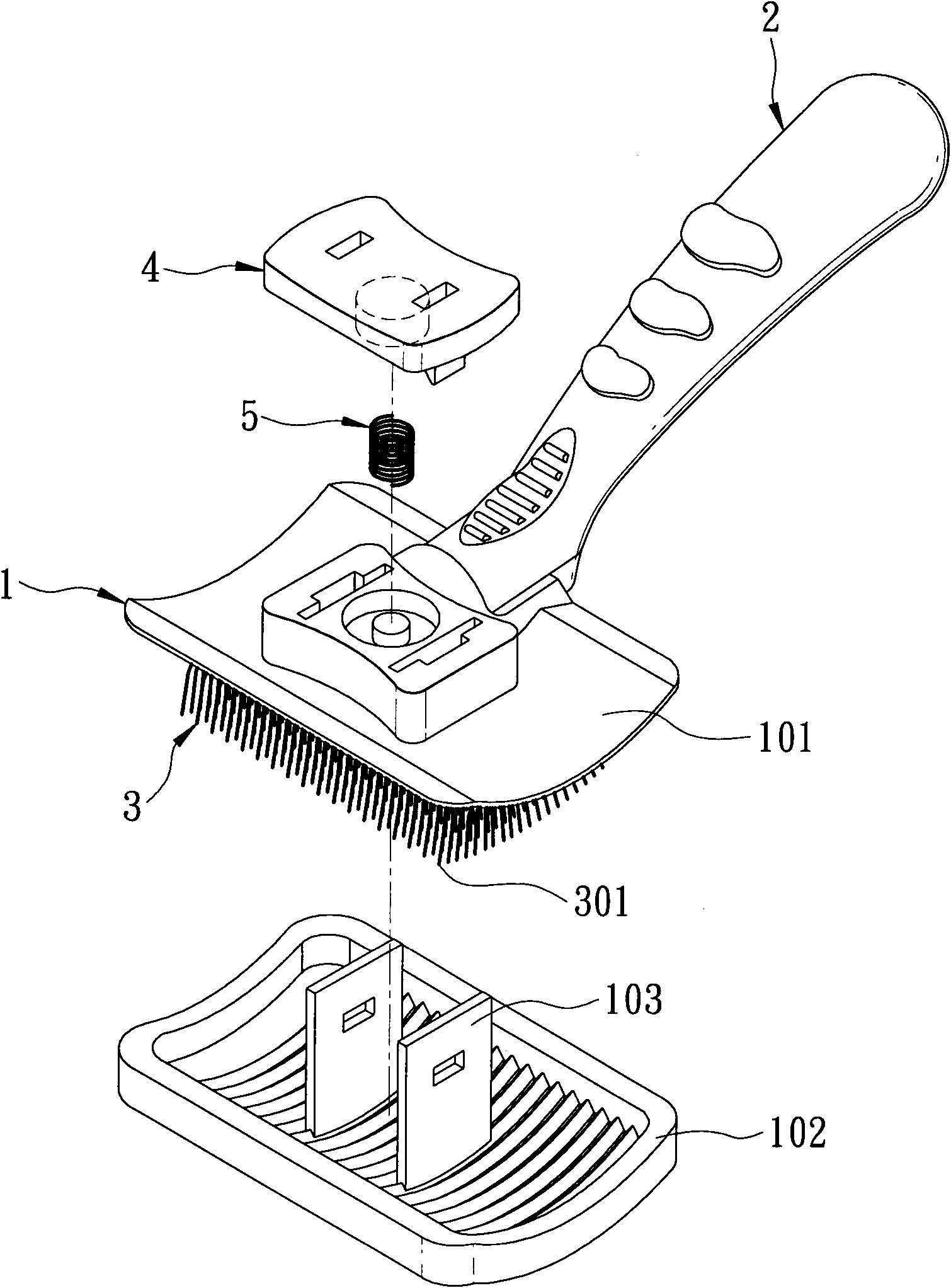
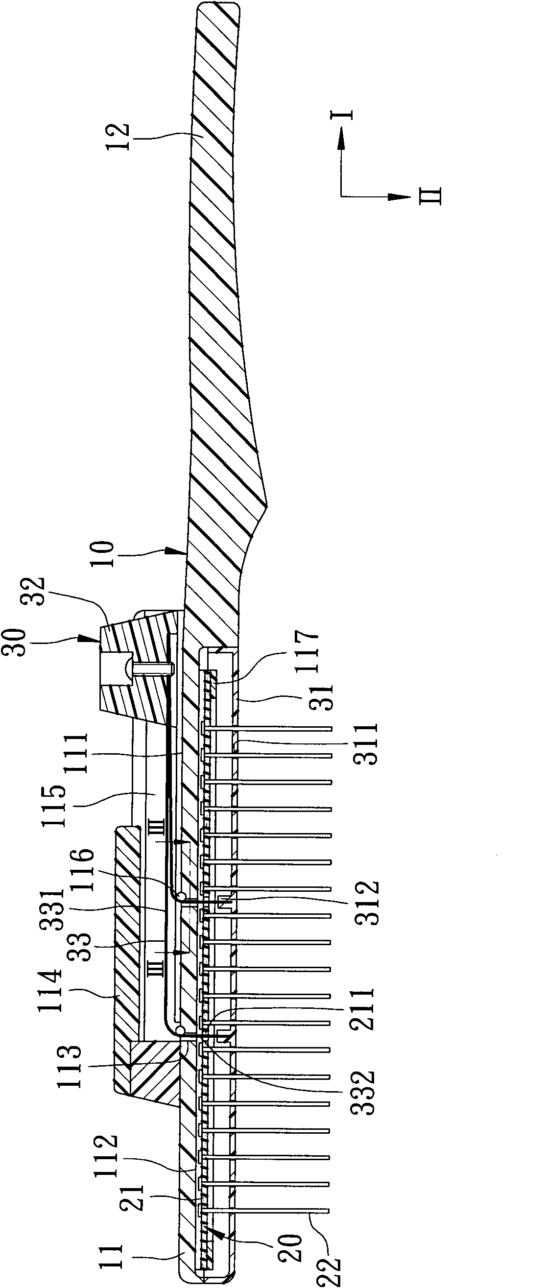
[0025] like figure 2 and Figure 4 As shown, the first preferred embodiment of the hair comb for removing snags of the present invention includes a body 10 , a comb unit 20 and a detent unit 30 .

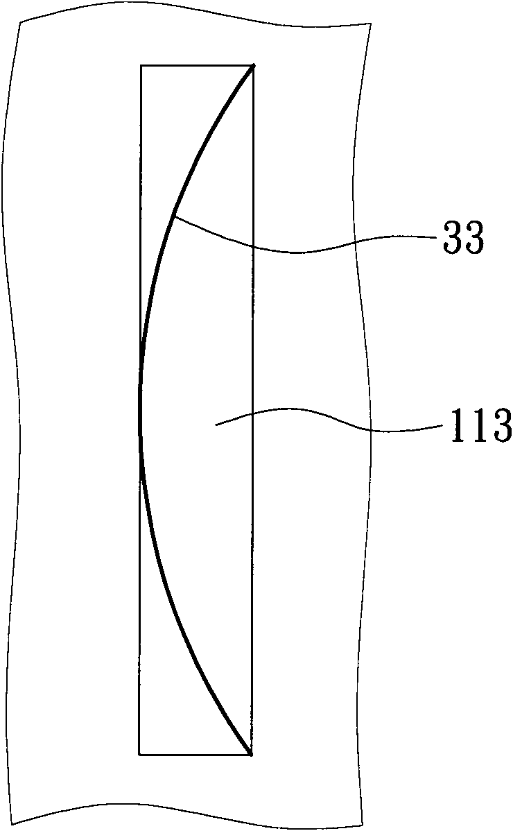
[0026] The body 10 extends along a first direction I, and has a comb base 11 and a handle 12 extending along the first direction I and connected to the comb base 11 . The comb base 11 has a top surface 111, a bottom surface 112 opposite to the top surface 111, two through holes 113 passing through the top surface 111 and the bottom surface 112, and a hollow boss 114 protruding from the top surface 111. and a guide portion 115 approaching the top surface 111 and extending along the first direction I, the through hole 113 is rectangular (see image 3 ), the guiding portion 115 is in the shape of a groove, and is disposed in the boss 114 . In addition, th...


PUM


Abstract

The invention relates to a hair comb capable of removing hooked hair. The hair comb comprises a body, a comb pin unit and a brake unit, wherein the body is provided with at least one through hole and a guide part which extends along a first direction; the comb pin unit is fixed on the body and is provided with a plurality of comb pins which extend along a second direction; and the brake unit is provided with a brake plate corresponding to the comb pin unit, a pushing piece which is sleeved in the guide part, and at least one flexible piece which is connected between the brake plate and the pushing piece. The pushing piece is operated to slide along the guide part, is linked with the brake plate through the flexible piece and is moved from an original position to a removing position, so that the aims of reducing overall height and miniaturizing products are fulfilled.

Description

technical field [0001] The invention relates to a hair grooming appliance, in particular to a hair comb capable of removing hook hairs. Background technique [0002] like figure 1 As shown, there is an existing hair comb (No. CN2901985Y) that can remove hook hair, which includes a comb base 1, a handle 2 connected to the comb base 1, a comb needle group 3, a control Part 4 and an elastic component 5. The comb base 1 has a top plate 101, a bottom plate 102 that can be separated from the top plate 101, and a guide portion 103 protruding from the bottom plate 102 and passing through the top plate 101. The comb set 3 is arranged on the top plate 101 The bottom has a plurality of comb needles 301, the control part 4 is connected to the top of the guide part 103, the elastic force of the elastic component 5 keeps the control part 4 away from the top board 101, and the bottom board 102 is stacked on the top board 101 in conjunction with it. When the control member 4 is pressed, ...

Claims


Application Information

Patent Timeline
Patent Type & Authority Applications(China)
IPC IPC(8): A45D24/42A45D24/04
Inventor 王火标
Owner 王火标
Why Eureka
Try Eureka