
Air preheater optical fiber temperature on-line monitoring system and method

An air preheater and monitoring system technology, applied to thermometers, thermometers with physical/chemical changes, instruments, etc., can solve problems such as fires, false alarms, fires and combustion of heating elements, and increase reliability and service life , the effect of improving reliability

Inactive Publication Date: 2012-03-28
SHANGHAI ORIENTAL MARITIME ENG TECH CO LTD
View PDF5 Cites 4 Cited by
  • Summary
  • Abstract
  • Description
  • Claims
  • Application Information

AI Technical Summary

Problems solved by technology

[0002] The air preheater is an important supporting equipment for large generator boilers. Inside the air preheater, the incompletely burned accumulation deposited on the surface of the heating element will easily generate hot spots when encountering sufficient oxygen at the air inlet. If the hot spots are slow Slow diffusion will cause the heating element to catch fire and form a fire, which will cause serious and irreparable losses. In order to prevent the air preheater from catching fire, it is necessary to install a monitoring device in the air preheater system. Commonly used are infrared hot spot detection detectors and thermocouple detectors, their detection mechanism adopts the point test method, and uses the absolute value of the comparison temperature to determine whether there is a hot spot. These devices still have some problems in terms of safety, reliability and service life, and are easy to false alarm

Method used


Image

  • Air preheater optical fiber temperature on-line monitoring system and method
  • Air preheater optical fiber temperature on-line monitoring system and method
  • Air preheater optical fiber temperature on-line monitoring system and method

Examples


Embodiment Construction

[0029] In order to make the technical means, technical features, invention objectives and technical effects realized by the present invention easy to understand, the present invention will be further described below in conjunction with specific illustrations.

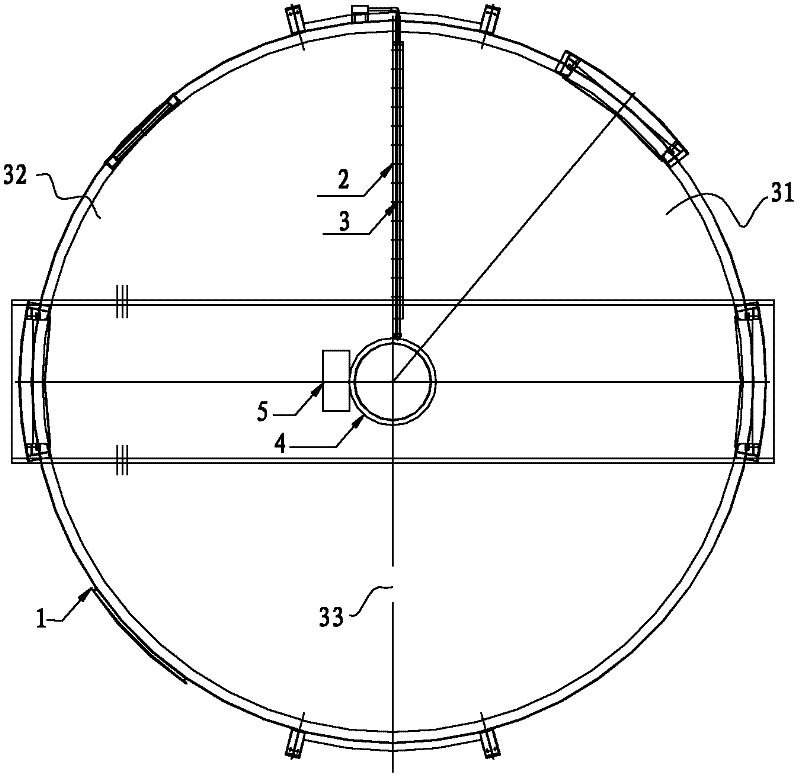
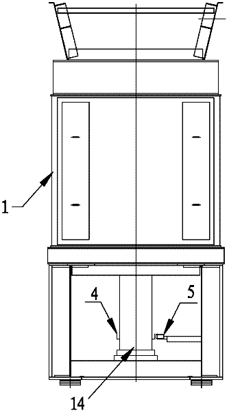
[0030] like figure 1 and Figure 1a As shown: the air preheater temperature optical fiber online monitoring system of the present invention includes a distributed optical fiber temperature sensor 3, a mounting bracket 2, a stop alarm device and a control cabinet 8, and the control cabinet 8 is connected to the distributed optical fiber temperature sensor 3. Stop alarm device, the area where the mounting bracket 2 is located is the secondary air side 32, adjacent to it is the primary air side 31, and the flue gas side 33; 4 sets of special The optical fiber temperature sensor 3 is installed inside the optical fiber temperature sensor mounting frame 2, refer to figure 2 , the optical fiber temperature sensor mounting f...


PUM


Abstract

The invention discloses an air preheater optical fiber temperature on-line monitoring system and an air preheater optical fiber temperature on-line monitoring method. The system comprises distributive optical fiber temperature sensors, a mounting bracket, a stall alarm device and a control cabinet, wherein the control cabinet is connected with the distributive optical fiber temperature sensors and the stall alarm device through signals; the optical fiber temperature sensors are arranged in an air preheater along the radium direction; a rotor of the air preheater is provided with a stall alarm device induction piece hoop; four sets of optical fiber temperature sensors are arranged in an optical fiber temperature sensor mounting frame. The distributive special optical fiber temperature sensors acquire temperature data, and ranges of monitoring blind spots and dead zones are greatly reduced; and by integrated control of a special analyzer, a programmable controller and a touch screen, man-machine conversation is realized, the reliability of the system is improved and the service life of the system is prolonged.

Description

technical field [0001] The invention relates to the technical field of air preheater temperature monitoring, in particular to an optical fiber online monitoring system and a monitoring method for the temperature of a preheater. Background technique [0002] The air preheater is an important supporting equipment for large generator boilers. Inside the air preheater, the incompletely burned accumulation deposited on the surface of the heating element will easily generate hot spots when encountering sufficient oxygen at the air inlet. If the hot spots are slow Slow diffusion will cause the heating element to catch fire and form a fire, which will cause serious and irreparable losses. In order to prevent the air preheater from catching fire, it is necessary to install a monitoring device in the air preheater system. Commonly used are infrared hot spot detection detectors and thermocouple detectors, their detection mechanism adopts the point test method, and uses the absolute val...

Claims


Application Information

Patent Timeline
Patent Type & Authority Applications(China)
IPC IPC(8): G01K11/32
Inventor 马玉顺匡俊秦海瑞杨晋慧沈海钢张春晖余天乐张海华华维敏杨迪
Owner SHANGHAI ORIENTAL MARITIME ENG TECH CO LTD
Learn More