
Crane

A technology of cranes, lifting hooks, applied in the direction of cranes, load lifting elements, transport and packaging

Active Publication Date: 2012-03-21
LIEBHERR WERK EHINGEN
View PDF5 Cites 5 Cited by
  • Summary
  • Abstract
  • Description
  • Claims
  • Application Information

AI Technical Summary

Problems solved by technology

Likewise, if a heavier load is applied to one rope, installing two separate ropes would subject the boom to additional side loads

Method used


Image

  • Crane
  • Crane
  • Crane

Examples


Embodiment Construction

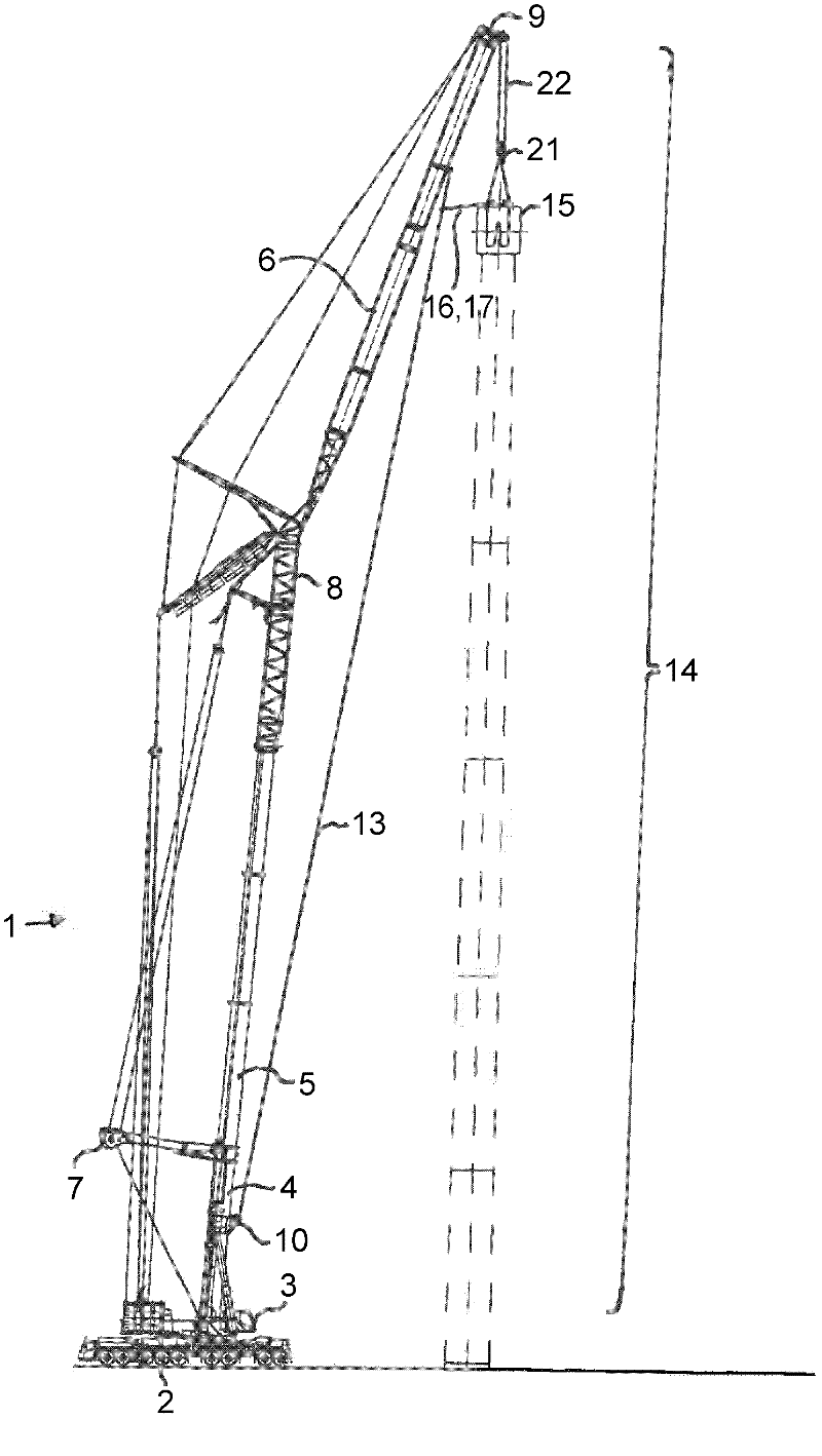
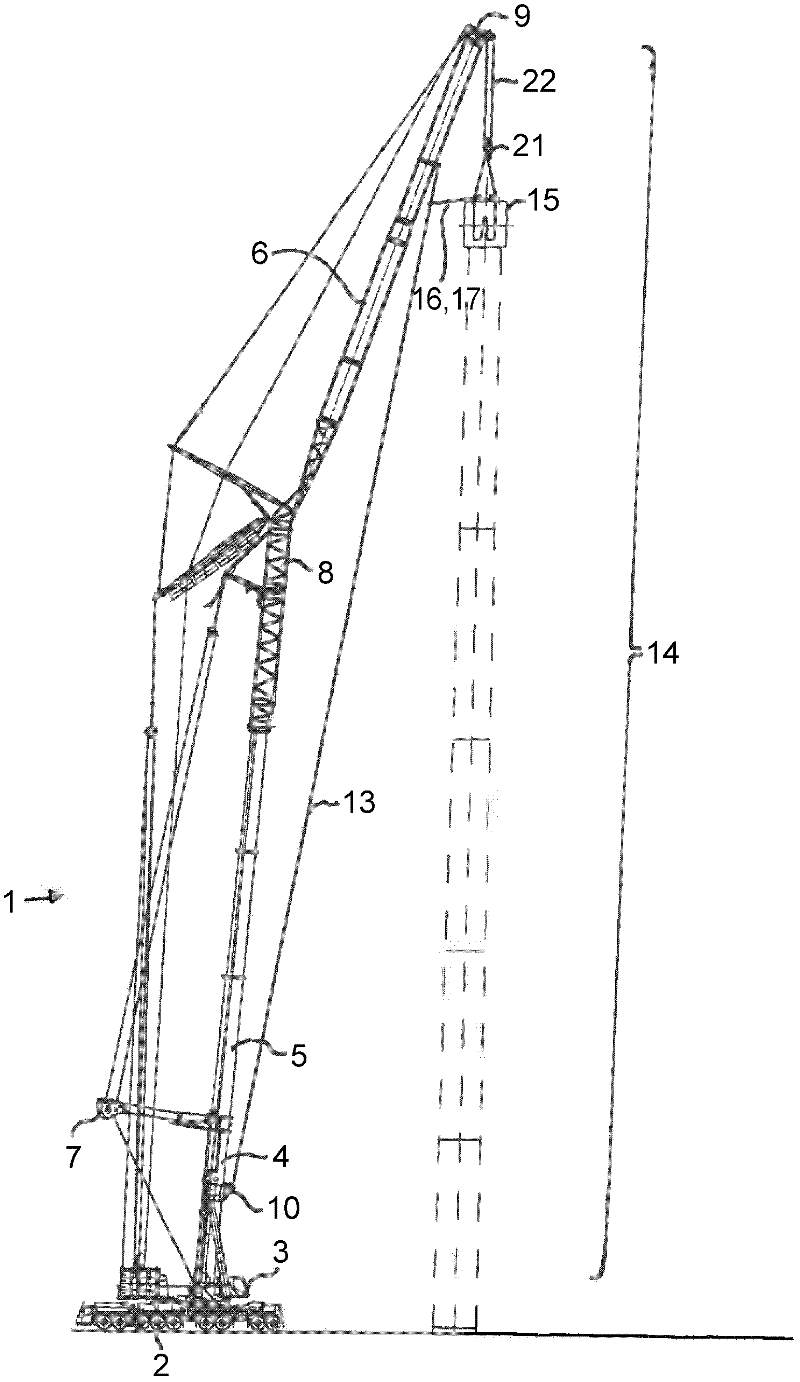
[0028] By known types and methods, in figure 1 The truck crane 1 shown in has an undercarriage 2 designed as a truck, on which an upper frame 3 is supported that can rotate about a vertical axis. The upper bracket 3 carries a cantilever system 14 capable of varying amplitude around a horizontal axis, which has an articulated arm section 4 hinged on the upper bracket 3 and a plurality of telescopic sections that can protrude therefrom. A variable-amplitude lattice boom 6 is arranged on the innermost telescopic joint of the main boom 5, and they can be connected by a lattice member. The main jib 5 is tensioned by means of a tensioning device 7 which is designed as a spatial, known Y-shaped tensioning device.

[0029] A hoisting rope 22 is guided over the luffing jib 6 via the deflection pulley 9 and carries the lifting hook 21 . A frame 15 is suspended on the lifting hook 21 , which serves to accommodate the rotor blades of the wind turbine, not shown in detail here.

[0030]...


PUM


Abstract

This invention relates to a crane, in particular a telescopic crane, with a frame suspended on the load hook for taking up a special load, in particular for taking up a rotor blade of a wind turbine. In accordance with the invention a single guide cable without guying function is provided, which proceeding from the boom foot is tensioned parallel to the direction of the longitudinal axis of the boom system and is attached to the boom system at its end, wherein a frame suspended on the load hook is connected with the guide cable via at least two control cables.

Description

technical field [0001] The invention relates to a crane, in particular a telescopic boom crane, with a frame suspended on a lifting hook, which is used to accommodate special loads, in particular to accommodate rotor blades of a wind power plant. Background technique [0002] During the installation of wind power plants, the rotor blades are brought to a great height. Preferably, a truck crane or a crawler crane is used for this purpose. The rotor blades to be installed have a large rotational surface and thus a large wind-acting surface. In order to mount the rotor blades on the corresponding wind turbine, it is necessary to adjust the lifted rotor blades to the installation height with sufficient precision. [0003] For this purpose, it is known from the prior art to accommodate the rotor blades by means of a frame. The frame is hung on the lifting hook of the hoisting cable and the rotation to be mounted is accommodated in a corresponding receptacle. [0004] For exam...

Claims


Application Information

Patent Timeline
Patent Type & Authority Applications(China)
IPC IPC(8): B66C23/62B66C1/16
CPCB66C13/06B66C13/08B66C1/108
Inventor 于格弗·里希特
Owner LIEBHERR WERK EHINGEN
Learn More