Heliostat calibration system of solar power station and calibration method
A calibration system and heliostat technology, applied in the field of solar power generation, can solve the problems of slow calibration of the heliostat calibration system, etc., and achieve the effects of fast calibration action, improved calibration accuracy and small mechanical error
- Summary
- Abstract
- Description
- Claims
- Application Information
AI Technical Summary
Problems solved by technology
Method used
Image

Examples
Embodiment 1
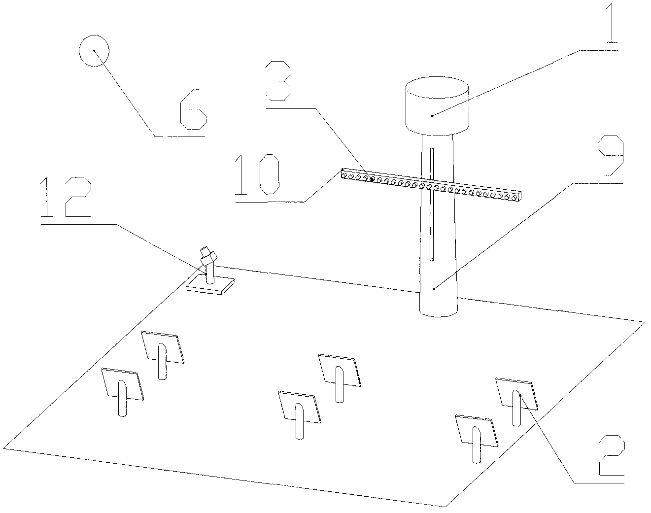
[0046] figure 2Shown is a heliostat calibration system for a solar power plant, which includes a receiver 1 mounted on a support tower 9 that receives sunlight reflected by a heliostat 2 to directly generate steam or electricity; The height of the receiver 1 from the ground ensures that all the heliostats 2 in the heliostat field can be reflected onto the receiver 1 .
[0047] It also includes a heliostat field installed around the receiver; the heliostat field includes at least one heliostat 2; the heliostat 2 is configured with two rotation axes, and the heliostat 2 revolves The rotating shaft performs pitching rotation and panning rotation; the dual rotating shafts are equipped with angle sensors, which are used to accurately measure the actual pitching angle that the two rotating shafts rotate through and the pan angle ω. The heliostat 2 tracks the moving sun by adjusting the orientation of the mirror, so that the sunlight is continuously reflected to the receiver 1 . ...
Embodiment 2
[0074] Figure 7 Shown is the heliostat calibration system of this embodiment. The difference between this calibration system and the calibration system in Embodiment 1 is that there is one image sensor in this embodiment, which is installed on the plane mounting bracket 10. It moves horizontally along the plane mounting bracket 10 and can move up and down along with the plane mounting bracket 10 . The moving range of the planar mounting bracket 10 , that is, the collecting range of the image sensor is isolated from the receiving range of the receiver 1 .
[0075] When the error of the heliostat is small, it is only necessary to calibrate the pitch angle and pan angle error of the heliostat. In this embodiment, the error that needs to be calibrated is: the pitch angle and the pan angle error of the heliostat, and the calibration process of the heliostat calibration system includes the following steps:
[0076] a. The control unit first controls the rotation of the heliostat ...
Embodiment 3
[0085] Figure 8It is the calibration system in this embodiment, which is basically the same as the calibration system in Embodiment 1, and its difference is that: the image sensor groups are 3 groups, which include the installation bracket 4 installed in the field of the heliostat Two groups of image sensors move up and down along the mounting bracket 4 . It also includes a group of image sensors installed on the plane mounting bracket 10, the plane mounting bracket 10 is located on the support tower 9 of the receiver 1, the image sensors are arranged in the horizontal direction, and they are arranged with the plane mounting bracket 10 Moving up and down. In this embodiment, the three groups of image sensors can calibrate image sensors in different areas within the heliostat field.
[0086] In this embodiment, the errors that need to be calibrated are: pitch angle and pan angle Non-perpendicularity η of two rotation axes 0 , the spatial position (x, y, z) of the mirror c...
PUM
 Abstract
Description
Claims
Application Information
 - R&D
- Intellectual Property
- Life Sciences
- Materials
- Tech Scout
- Unparalleled Data Quality
- Higher Quality Content
- 60% Fewer Hallucinations
Browse by: Latest US Patents, China's latest patents, Technical Efficacy Thesaurus, Application Domain, Technology Topic, Popular Technical Reports.
© 2025 PatSnap. All rights reserved.Legal|Privacy policy|Modern Slavery Act Transparency Statement|Sitemap|About US| Contact US: help@patsnap.com