
Clamping device

A clamping device and clamping piece technology, applied in the direction of chucks, manipulators, manufacturing tools, etc., can solve the problems of large size, uncompact structure, and large space occupation of the clamping device, so as to reduce the size and achieve sufficient structure. compact effect

Inactive Publication Date: 2015-03-25
中山市云创知识产权服务有限公司
View PDF7 Cites 0 Cited by
  • Summary
  • Abstract
  • Description
  • Claims
  • Application Information

AI Technical Summary

Problems solved by technology

However, because the first clamping arm and the second clamping arm move in translation, the size of the clamping device in the clamping direction is relatively large, which requires a large space and the structure is not compact

Method used


Image

  • Clamping device
  • Clamping device
  • Clamping device

Examples


Embodiment Construction

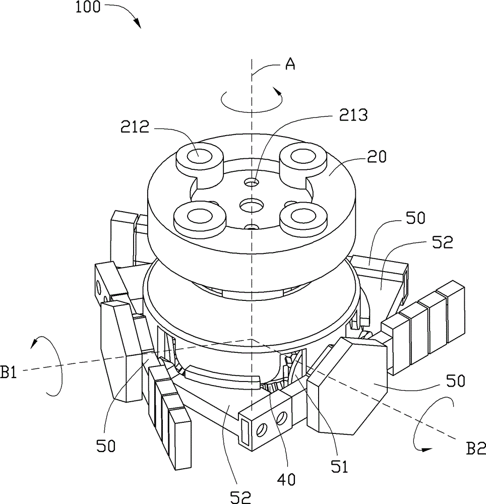
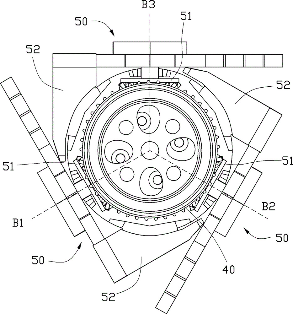
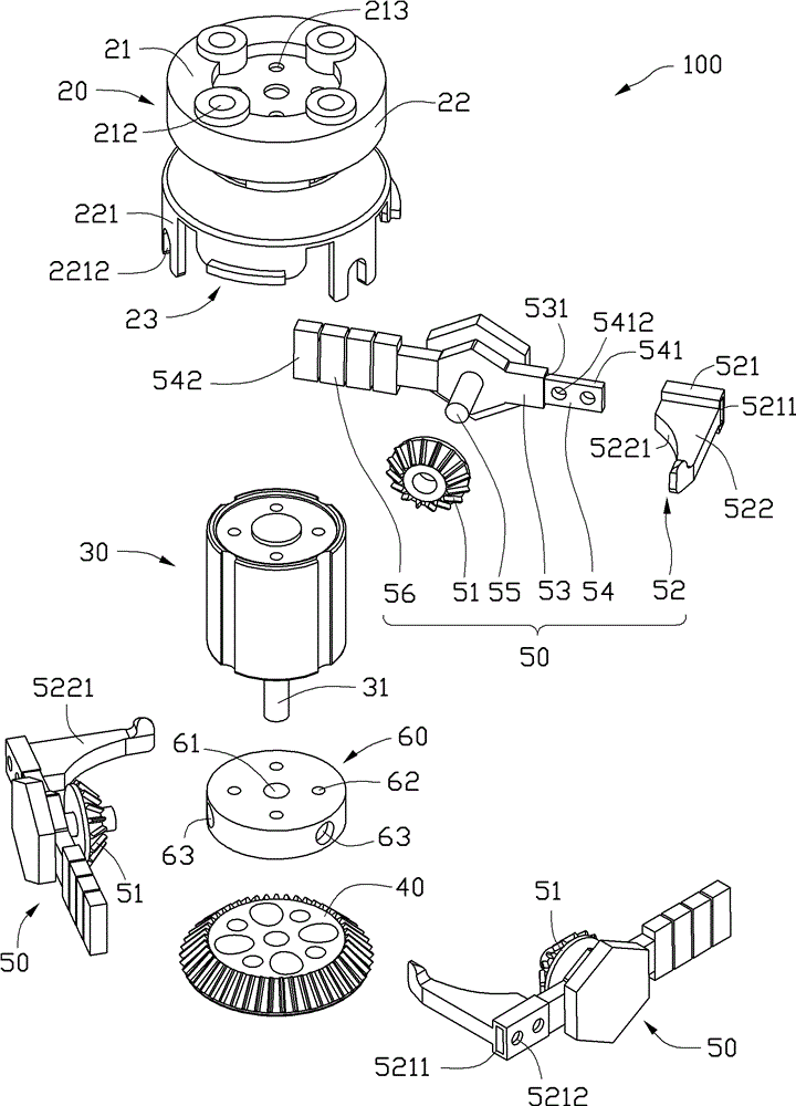
[0013] see Figure 1 to Figure 3 , The clamping device 100 according to the embodiment of the present invention includes a mounting base body 20 , a rotating driving member 30 disposed on the mounting base body 20 , a driving bevel gear 40 driven by the rotating driving member 30 and three clamping jaw assemblies 50 .

[0014] Each jaw assembly 50 includes a driven bevel gear 51 meshing with the driving bevel gear 40 and a clamping member 52 driven by the driven bevel gear 51 . The three jaw assemblies 50 surround the mounting base body 20 and are arranged at equal intervals in the circumferential direction. When the rotary driving member 30 drives the driving bevel gear 40 to rotate, the driven bevel gear 51 rotates accordingly, so that the clamping member 52 is relatively closed or opened to clamp or loosen the workpiece to be clamped.

[0015] In this embodiment, the driving bevel gear 40 rotates around the axis A, and the three driven bevel gears 51 respectively rotate ar...


PUM


Abstract

The invention discloses a clamping device, which comprises a mounting seat body, a rotary driving member, at least two clamping jaw components and a driving bevel gear, wherein the rotary driving member is arranged on the mounting seat body; the clamping jaw components can rotate relative to the mounting seat body; the driving bevel gear is driven by the rotary driving member; and each clamping jaw component comprises a driven bevel gear which is engaged with the driving bevel gear and a clamping member which is driven by the driven bevel gear. The clamping device has the advantages of compact structure.

Description

technical field [0001] The invention relates to a clamping device. Background technique [0002] An existing clamping device applied to a manipulator includes a first clamping arm, a second clamping arm and a linear drive member which are oppositely arranged. The opposite ends of the first clamping arm and the second clamping arm are formed with clamping surfaces adapted to the workpiece to be clamped. The linear drive is generally an air cylinder. Driven by the linear drive, the first clamping arm and the second rotary drive move toward each other along a clamping direction, so that the clamping device switches between the clamping state and the open state. However, because the first clamping arm and the second clamping arm move in translation, the size of the clamping device in the clamping direction is relatively large, which requires a relatively large space and is not compact in structure. Contents of the invention [0003] In view of the above, it is necessary to p...

Claims


Application Information

Patent Timeline
Patent Type & Authority Patents(China)
IPC IPC(8): B25J15/00
Inventor 李昇军梁献全许寿国
Owner 中山市云创知识产权服务有限公司
Learn More