Structure of protecting appearances of metal inserts in mould

A technology of metal inserts and appearance, applied in the direction of coating, etc., can solve the problems of high cost, surface strain of metal inserts, mold core strain, etc.

Inactive Publication Date: 2012-01-25
VANGUARD TECH WUXI
View PDF3 Cites 4 Cited by
  • Summary
  • Abstract
  • Description
  • Claims
  • Application Information

AI Technical Summary

Problems solved by technology

[0002] In the existing injection molds, it is often encountered that the metal insert is placed inside the mold first, and then injected. Since the metal insert directly contacts the mold core, it is easy to cause the surface of the metal insert to be scratched and the mold core to be strained. , leading to high production costs

Method used


Image

  • Structure of protecting appearances of metal inserts in mould
  • Structure of protecting appearances of metal inserts in mould

Examples


Embodiment Construction

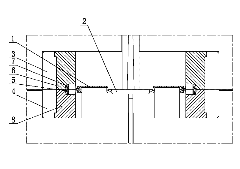
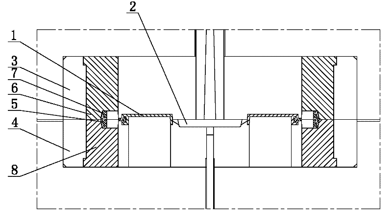
[0007] See figure 1 , which includes product cavity 1, runner 2, front mold core 3, rear mold core 4, metal insert 5, flow channel 2 connected to product cavity, metal insert 5 connected to product cavity 1, and metal insert 5 outside An engineering plastic sleeve is installed between the surface and the inner surface of the front mold core 3 and the rear mold core 4, the outer surface of the metal insert 5 fits the installation groove 7 on the inner surface of the engineering plastic sleeve, and the outer surface of the engineering plastic sleeve The surface fits the inner surfaces of the front mold core 3 and the rear mold core 4. The engineering plastics sleeve is formed by joining the upper sleeve 6 and the lower sleeve 8, and the installation groove 7 on the inner surface is formed by joining the upper sleeve 6 and the lower sleeve 8.


PUM


Abstract

The invention provides a structure of protecting appearances of metal inserts in a mould, which is characterized in that the surfaces of the metal inserts are not easy to pull, mould cores are not easy to pull, and further, the production cost is low. The structure of protecting the appearances of the metal inserts in the mould comprises product mould cavities, a runner, a front mould core, a rear mould core and the metal inserts, wherein the runner is communicated with the product mould cavities, and the metal inserts are communicated with the product mould cavities. The structure of protecting the appearances of the metal inserts in the mould is characterized in that engineering plastic sleeves are respectively arranged between the outer surfaces of the metal inserts and the inner surfaces of the front mould core and the rear mould core; the outer surfaces of the metal inserts are fitted with mounting slots on the inner surfaces of the engineering plastic sleeves; and the outer surfaces of the engineering plastic sleeves are fitted with the inner surfaces of the front mould core and the rear mould core.

Description

technical field [0001] The invention relates to the technical field of mold structure, in particular to a structure for protecting the appearance of metal inserts in the mold. Background technique [0002] In the existing injection molds, it is often encountered that the metal insert is placed inside the mold first, and then injected. Since the metal insert directly contacts the mold core, it is easy to cause the surface of the metal insert to be scratched and the mold core to be strained. , leading to high production costs. Contents of the invention [0003] In view of the above problems, the present invention provides a structure for protecting the appearance of the metal insert in the mold, which makes the surface of the metal insert less likely to be scratched and the core of the mold less likely to be strained, thereby reducing the production cost. [0004] The structure for protecting the appearance of the metal insert in the mold has a technical scheme as follo...

Claims


Application Information

Patent Timeline
Patent Type & Authority Applications(China)
IPC IPC(8): B29C45/26B29C45/14
Inventor 张卫
Owner VANGUARD TECH WUXI
Why Eureka
Try Eureka