
Curved labyrinth seal

A bending and sealing convex technology, which is applied in the direction of engine sealing, engine manufacturing, machine/engine, etc., can solve problems such as leakage

Inactive Publication Date: 2012-01-18
GENERAL ELECTRIC CO
View PDF10 Cites 28 Cited by
  • Summary
  • Abstract
  • Description
  • Claims
  • Application Information

AI Technical Summary

Problems solved by technology

However, fluid can flow through this interface to areas of lower pressure, which can lead to larger leaks

Method used


Image

  • Curved labyrinth seal
  • Curved labyrinth seal
  • Curved labyrinth seal

Examples


Embodiment Construction

[0107] One or more specific embodiments of the invention will be described below. In an effort to provide a concise description of these embodiments, not all features of an actual implementation may be described in the specification. It should be appreciated that in the development of any such practical implementation (as in any engineering or design project), many specific implementation decisions must be made to achieve the developer's specific goals, such as compliance with system-related and business-related constraints, for different implementations way, these constraints can be different. Furthermore, it should be appreciated that such a development effort might be complex and time consuming, but would nevertheless be a routine undertaking of design, fabrication, and manufacture for those of ordinary skill in the art having the benefit of this disclosure.

[0108] When introducing elements of various embodiments of the present invention, the articles "a," "the," and "sa...


PUM


Abstract

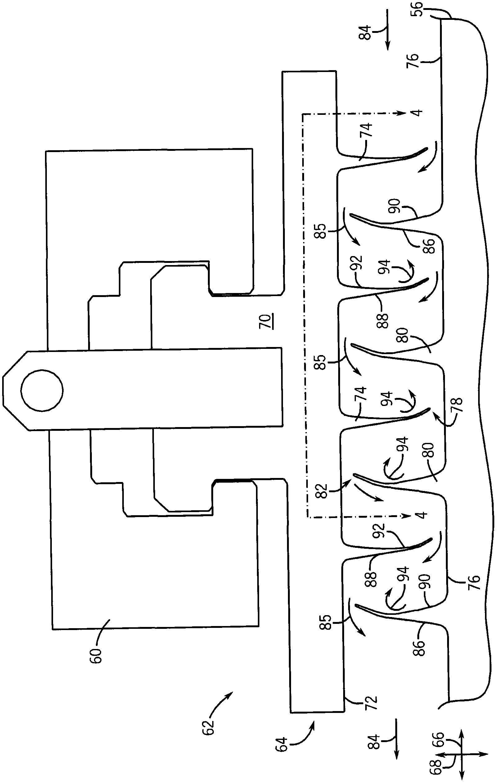
The application refers to curved labyrinth seal. In one embodiment, a system includes a rotary machine (12) and a packing seal (62) that is disposed between rotary and stationary components of the rotary machine. The packing seal (62) includes a pair of seal lands (80) spaced axially (66) along the rotary component and a seal tooth (74) disposed at an axial position between the pair of seal lands (80). At least one seal land (80) of the pair of seal lands (80) or the seal tooth (74) includes a curved flow-facing side (90, 92) and is slanted toward the curved flow-facing side (90, 92).

Description

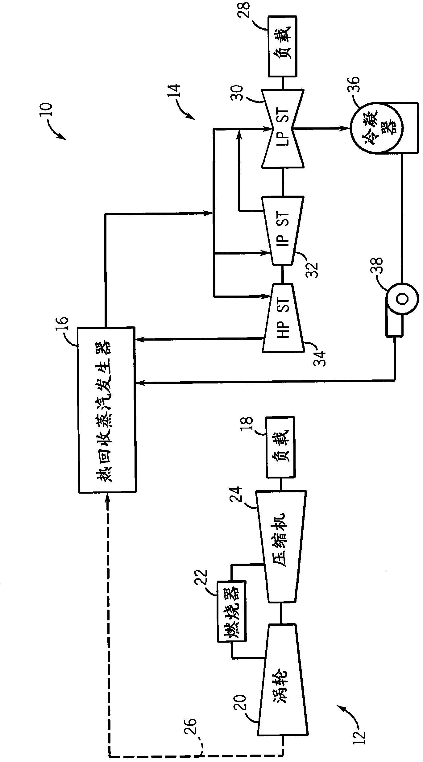
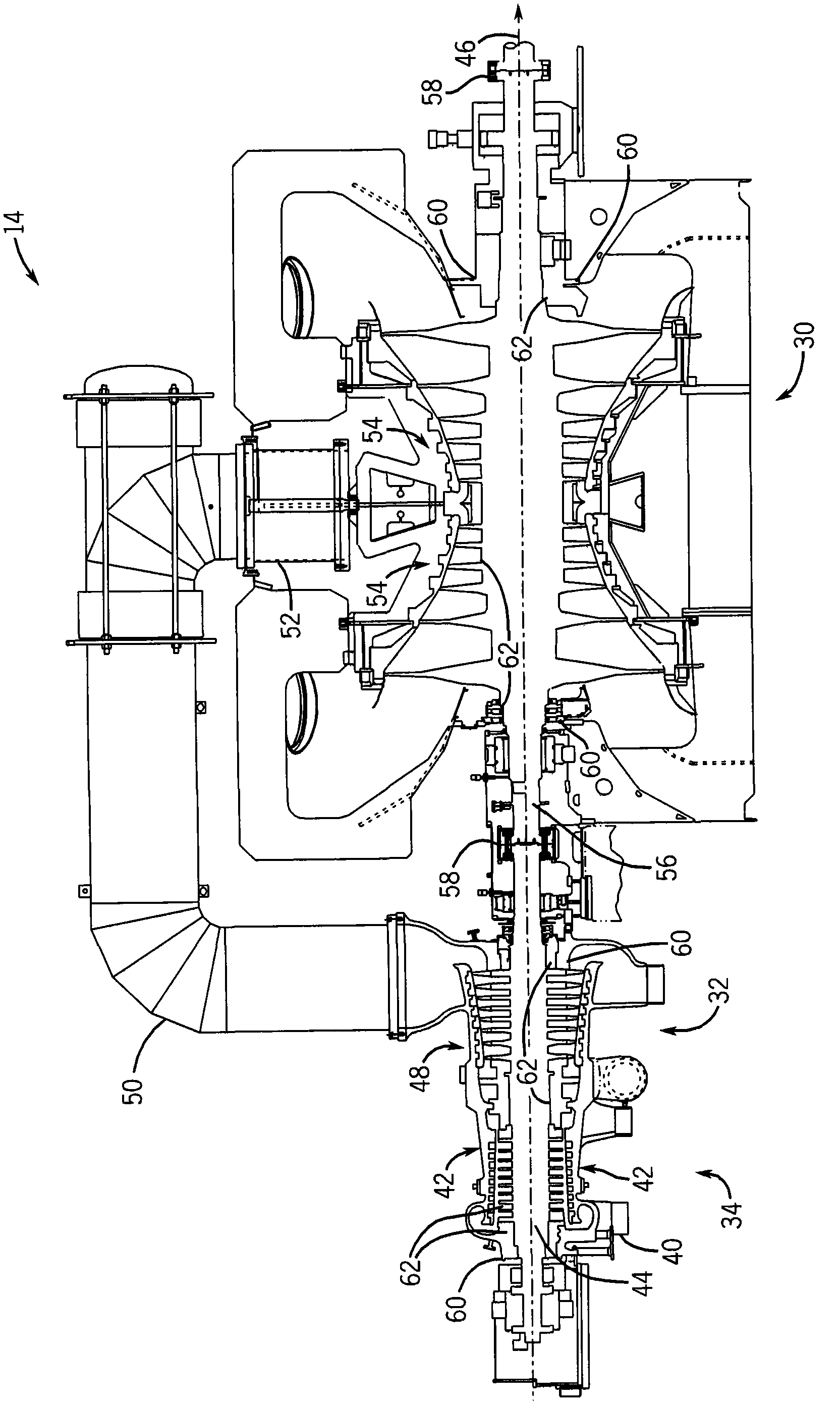
technical field [0001] The subject matter disclosed herein relates to packing seals, and more particularly to curved labyrinth packing seals used in rotary machines. Background technique [0002] In general, packing seals are used between rotating and stationary parts in rotating machines such as steam turbines, gas turbines, generators, and compressors. Rotary machines flow fluid between one or more stages of rotating components to generate power or to compress the fluid. Packing seals may be located between stages, at the inlets of stages and / or at the outlets of stages to reduce fluid leakage between stationary and rotating components. A packing seal typically includes a series of teeth that interface with a seal land to form a restriction that inhibits fluid flow. However, fluid can flow through this interface to areas of lower pressure, which can lead to larger leaks. Contents of the invention [0003] Certain embodiments of the invention commensurate in scope with...

Claims


Application Information

Patent Timeline
Patent Type & Authority Applications(China)
IPC IPC(8): F16J15/447
CPCF01D11/02F01D11/001F05D2250/71F05D2250/712F16J15/4472F05D2250/711
Inventor U·加格S·库马P·莫达楚尔克里斯南
Owner GENERAL ELECTRIC CO
Learn More