
Electric bus battery box locking and unlocking device

A technology for electric passenger cars and unlocking devices, which is applied in the direction of electric power devices, electric vehicles, power devices, etc., can solve problems such as deformation of the battery box, deformation of the lock tongue, and inability to retract the electromagnetic lock, so as to avoid mutual interference and improve the unlocking force. Reliable effect of shrinking and locking

Active Publication Date: 2013-08-07
KUNMING SHIPBUILDING EQUIP
View PDF4 Cites 0 Cited by
  • Summary
  • Abstract
  • Description
  • Claims
  • Application Information

AI Technical Summary

Problems solved by technology

The disadvantage is that when the battery inner box is pushed into the battery outer box, if the inner box is not pushed in place, the bolt of the electromagnetic lock cannot be inserted into the lock hole or the electromagnetic lock block, so the battery inner box cannot be locked. ; When the bolt of the electromagnetic lock is inserted into the lock hole, the electromagnetic lock only acts as a stopper, that is, to prevent the battery inner box from sliding out of the outer box, but it cannot ensure that the battery inner box and the outer box are tightly combined
In this locking method, the inner box will impact the bolt of the electromagnetic lock during the bumping of the vehicle. The long-term impact will cause the deformation of the bolt and the battery box, and eventually the electromagnetic lock cannot be retracted.
A Chinese patent with the publication number CN101289056 discloses a quick-change electric vehicle battery box that adopts a mechanical bolt-type locking, uses the return spring force to make the deadbolt protrude, and utilizes structures such as cams, swing arms, and connecting rods to lock the lock. The tongue is retracted to realize the locking and unlocking of the battery box. The disadvantage is that the bolt-type locking method cannot apply a locking force to the battery box, and only serves as a stopper.

Method used


Image

  • Electric bus battery box locking and unlocking device
  • Electric bus battery box locking and unlocking device
  • Electric bus battery box locking and unlocking device

Examples


Embodiment Construction

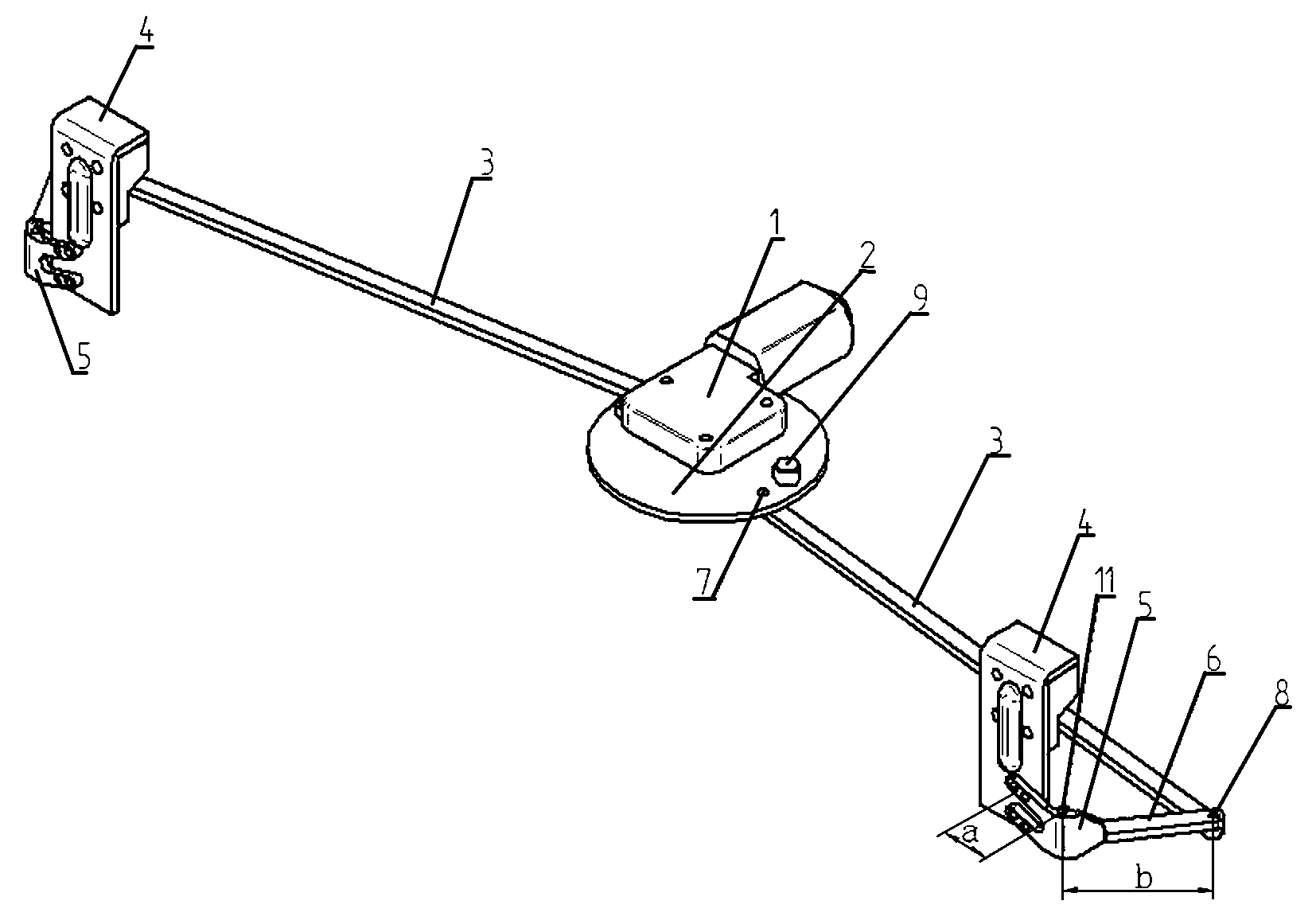
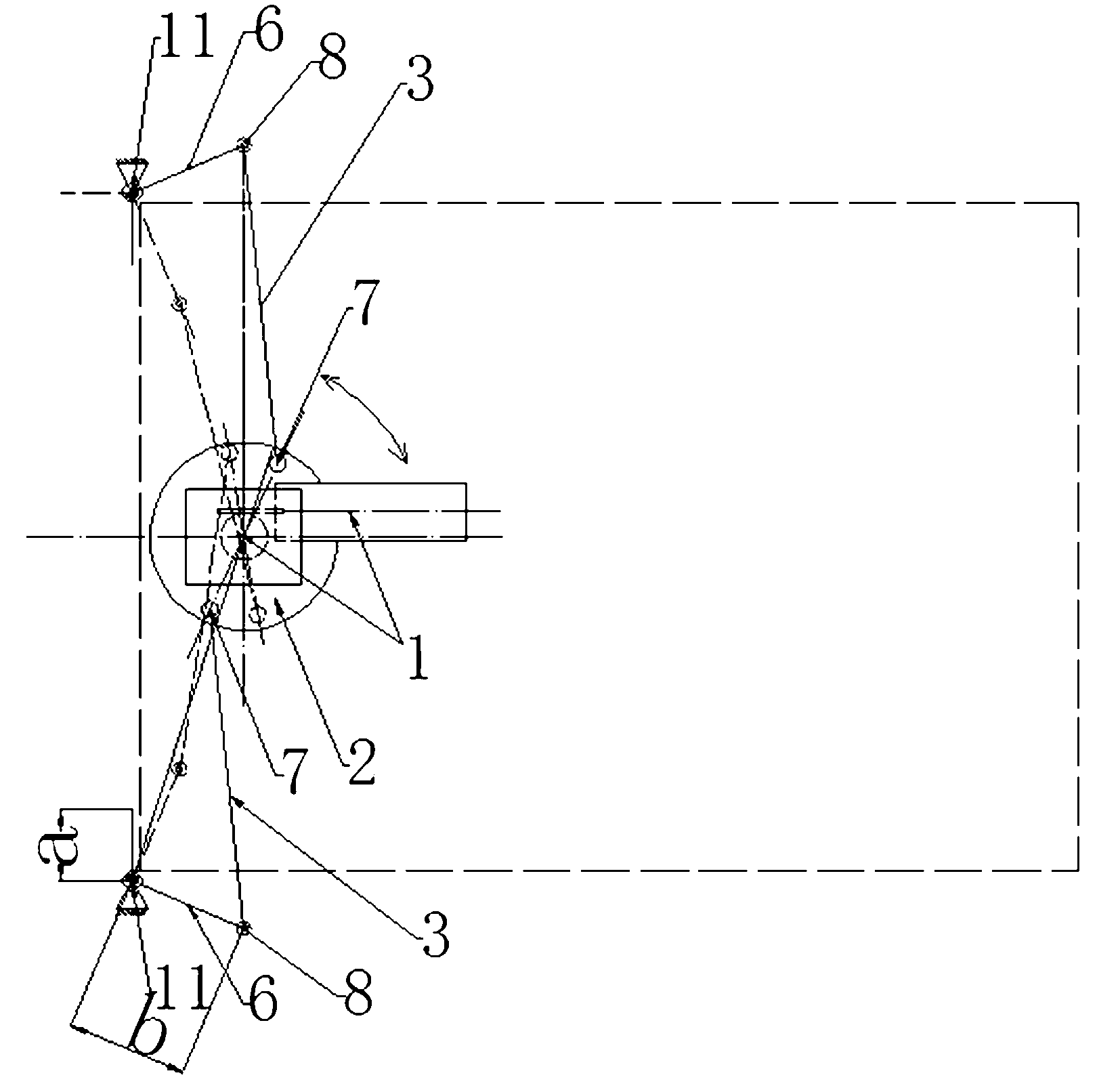
[0017] like figure 1 , figure 2 The shown locking and unlocking device for the battery box of an electric bus includes a worm gear motor 1, a turntable 2 connected to the output shaft of the worm gear motor 1 and placed at the bottom of the worm gear motor, and two symmetrically connected to both sides of the turntable through a pin shaft 7. A connecting rod 3, two rockers 6 symmetrically connected to the other ends of the two connecting rods 3 through rotating pins 8, two L-shaped curved plates 5 symmetrically fixedly connected to the outer ends of the rocking rods, and symmetrically connected to the L-shaped Two wedge-shaped pressing block members 4 at the other end of the bent plate. In this embodiment, the L-shaped bent plate 5 is a hand-shaped bent plate. Reinforcing ribs are arranged on the L-shaped bent plate. The rocker and the L-shaped bent plate can be connected by welding, or can be fixedly connected by other mechanical connection methods. A pin hole is provide...


PUM


Abstract

The invention discloses an electric bus battery box locking and unlocking device, which comprises a worm gear and worm motor (1), a turntable (2) connected with the output shaft of the worm gear and worm motor (1) and arranged at the bottom of the worm gear and worm motor, two connecting rods (3) symmetrically connected to two sides of the turntable through pin shafts (7), two swing rods (6) symmetrically connected to the other ends of the two connecting rods (3) through rotating pins (8) respectively, two L-shaped bent plates (5) symmetrically and fixedly connected to the outer ends of the swing rods, and two wedge-shaped pressure block members (4) symmetrically connected to the other ends of the L-shaped bent plates. The device can automatically apply a locking force to a battery box, so that the battery box is tightly combined with the vehicle body, jump and impact of the battery box in jolt are effectively prevented, and running safety of the vehicle is ensured; and meanwhile, thedevice is convenient for unlocking to realize quick change of the battery box.

Description

technical field [0001] The invention belongs to the structural technical field of a mechanical locking device for a battery box of an electric vehicle. Background technique [0002] Under the trend of countries around the world encouraging the development of the electric vehicle industry, battery technology, one of the key technologies of electric vehicles, has also received increasing attention. Come higher demands. One of the difficulties to be solved in the current electric vehicle battery replacement technology is how to automatically lock and unlock the battery box mounted on the vehicle safely and reliably. Most of the existing locking and unlocking technologies adopt a bolt-type locking method. For example, the general battery box disclosed by the Chinese patent whose publication number is CN101118957 has adopted the bolt-type locking realized by electromagnets from both sides of the battery box, electromagnetic locks are installed on the left and right sides of the...

Claims


Application Information

Patent Timeline
Patent Type & Authority Patents(China)
IPC IPC(8): B60K1/04B60L11/18
CPCY02T10/7005Y02T10/70
Inventor 李涛田华亭傅亚力张智勇
Owner KUNMING SHIPBUILDING EQUIP
Learn More