
hybrid drive

A technology of hybrid power and driving devices, which is applied in the direction of power devices, hybrid vehicles, pneumatic power devices, etc., can solve the problems of delay in pump speed and poor response of lock-up clutch control, and achieve the elimination of torque errors and high The effect of precision

Inactive Publication Date: 2011-12-28
AISIN AW CO LTD
View PDF5 Cites 45 Cited by
  • Summary
  • Abstract
  • Description
  • Claims
  • Application Information

AI Technical Summary

Problems solved by technology

[0014] However, since the control responsiveness of the lock-up clutch is usually not good, even if the lock-up clutch is controlled to slip, the rise of the pump rotation speed is delayed.
For this reason, if the target rotational speed of the motor is determined without considering the control response delay of the lock-up clutch, much torque will be transmitted through the lock-up clutch, so the torque transmitted to the transmission cannot be controlled according to the target.

Method used


Image

  • hybrid drive
  • hybrid drive
  • hybrid drive

Examples


Embodiment Construction

[0064] Embodiments of the present invention will be described based on the drawings.

[0065] The hybrid drive device 2 of the present embodiment includes an engine start control unit 3 as an engine start control device 1 .

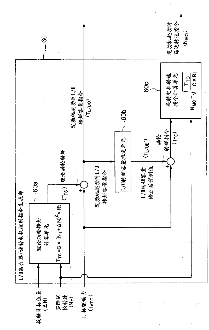
[0066] figure 1 It is a schematic diagram showing the configuration of a drive transmission system and a signal system of the hybrid drive device 2 according to the present embodiment. In this figure, a thick solid line indicates a transmission path of a driving force, and a thin solid line indicates a signal transmission system. As shown in the figure, the hybrid drive device 2 is schematically configured to include an engine 11 and a rotating electric machine 12 as a driving force source 13, and the driving force of these driving force sources 13 is transmitted through a torque converter 14 and a transmission. 15 to the wheels 18 for transmission. In addition, the hybrid drive device 2 includes a hydraulic control device (not shown) for supplying hy...


PUM


Abstract

Provided is a hybrid driving device capable of transmitting a target torque to a speed change gear without deficiency and without excess, regarding a technology of starting up an engine by a driving force of a rotating electrical machine during EV driving. The hybrid driving device is provided with a rotating electrical machine which is connected to a speed change gear through a hydraulic power transmission having a lockup clutch; and an engine start control device which starts an engine by controlling the number of rotations so that the number of rotations of the rotating electrical machine becomes a target number of rotations, by slipping the lockup clutch, prior to starting the engine. A transmission torque estimation means for estimating a transmission torque which is transmitted by the lockup clutch, under the condition that the lockup clutch slips, and a target rotation number determination means for determining a target number of rotations regarding the rotation number control for the rotating electrical machine, on the basis of the transmission torque estimated by the transmission torque estimation means, a target input torque to the speed change gear, and an actual turbine rotation number, are provided. The engine start control device controls the velocity so that the rotating electrical machine has the determined target number of rotations.

Description

technical field [0001] The present invention relates to techniques for starting an engine with a rotating electrical machine in a parallel hybrid drive. Background technique [0002] So-called parallel hybrid drives are known, which have: a rotating electric machine connected to the engine by means of a transmission clutch; a fluid transmission with a lock-up clutch, and has a pump wheel and a turbine; The motor is connected to input the driving force generated from one or both of the engine and the rotating electric machine as the driving force source, and the input driving force is outputted while changing the speed. [0003] In the parallel hybrid drive system, the engine is started by transmitting a part of the driving force generated from the rotating electric machine to the engine from a so-called EV running state in which only the driving force generated from the rotating electric machine is output to drive the vehicle. [0004] The engine start of this method refers...

Claims


Application Information

Patent Timeline
Patent Type & Authority Applications(China)
IPC IPC(8): B60W10/06B60K6/48B60K6/54B60L11/14B60W10/02B60W10/08B60W20/00F02D29/02F02N11/04F02N11/08F16H61/14B60L50/16
CPCB60W20/00B60W10/10B60W10/026B60W2510/0638B60L2240/421B60K6/547B60K6/365F16H61/143F16H2059/467B60W10/08B60W2510/1025B60W10/06Y02T10/6221B60W2510/081Y02T10/642B60K6/48B60W2710/081B60W30/192B60L2240/486B60L2240/441Y02T10/6286Y02T10/62Y02T10/64B60K2006/268B60W2510/105F02N7/12
Inventor 吉田高志白村阳明久田秀树大野佳纪
Owner AISIN AW CO LTD
Learn More