Photobioreactor
A technology of photobioreactor and photobiological cultivation, which is applied in the direction of photobioreactor, bioreactor/fermenter combination, specific-purpose bioreactor/fermenter, etc. Reactor dead angle, inconvenient assembly and movement, etc., to achieve the effect of simple structure, convenient cleaning, and easy harvesting
- Summary
- Abstract
- Description
- Claims
- Application Information
AI Technical Summary
Problems solved by technology
Method used
Image

Examples
Embodiment 1
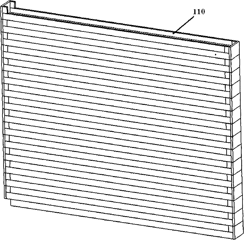
[0086] The photobioreactor provided by Embodiment 1 of the present invention is as figure 1 As shown, it includes: several containers 110 .
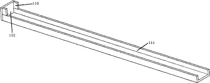
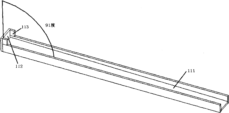
[0087] Wherein, the structure of the container 110 is as figure 2 As shown, the shape of the container 110 is like a tank with one end closed, one end is an open end, and the other end is a closed end. length of the side fence 113 .
[0088] The above-mentioned several containers 110 are stacked and staggered, and the open end of the container 110 on the upper layer is placed corresponding to the closed end of the container 110 on the next layer; The sides of 113 are joined to form a photobioreactor with fluid communication.
[0089] That is to say, when assembling the photobioreactor, first get a container 110 and place it on the lowermost layer, and then get another container 110 and place it on the lowermost container 110 as the second layer; the opening of the container 110 of the second layer The closed ends of the containers 1...
Embodiment 2
[0099] The photobioreactor provided by the second embodiment of the present invention is as Figure 6 As shown, the difference from the photobioreactor in the first embodiment is that the photobioreactor also includes at least one column 120 in addition to several containers 110 .
[0100] The columns 120 are arranged outside the side walls and / or outside the closed baffles of the assembled containers 110 to maintain the stability of the assembled photobioreactor. The columns 120 may not be connected and fixed with the reactor, but only play the role of support, stability and guidance, which expands the selection range of materials for the columns 120 and reduces the cost.
[0101] After the number of layers of the container 110 is increased, the stability of the reactor is weakened when the number of layers is relatively small. In order to ensure the overall stability of the photobioreactor, a column 120 can be set on the periphery of the photobioreactor to ensure the reactio...
Embodiment 3
[0104] The photobioreactor provided by the third embodiment of the present invention is as Figure 7 As shown, the difference from the photobioreactor in the second embodiment is that the photobioreactor not only includes several containers 110 and several columns 120 , but also includes: at least one support plate 130 connected to each column 120 .
[0105] A cross-sectional view of the bioreactor is shown in Figure 8 shown. Wherein, the support plates 130 at the same height on different columns 120 form a support plate group, and several containers 110 are divided into several container groups by the support plate group; each support plate group is used to support a group of containers located above itself Assembled container group.
[0106] After the number of layers of the container increases, the weight borne by the container 110 at the bottom of the reactor will also increase. In order to reduce the load on the bottom reactor, the support for its supporting function c...
PUM
 Abstract
Description
Claims
Application Information
 - R&D
- Intellectual Property
- Life Sciences
- Materials
- Tech Scout
- Unparalleled Data Quality
- Higher Quality Content
- 60% Fewer Hallucinations
Browse by: Latest US Patents, China's latest patents, Technical Efficacy Thesaurus, Application Domain, Technology Topic, Popular Technical Reports.
© 2025 PatSnap. All rights reserved.Legal|Privacy policy|Modern Slavery Act Transparency Statement|Sitemap|About US| Contact US: help@patsnap.com