
Method and control circuit for controlling physical layer chip

A physical layer chip and control circuit technology, applied in the field of communication, can solve the problems of increasing the burden on the CPU and the inability of the MDIO controller to control multiple PHY chips at the same time, and achieve the effect of reducing the burden

Inactive Publication Date: 2011-12-21
RUIJIE NETWORKS CO LTD
View PDF3 Cites 27 Cited by
  • Summary
  • Abstract
  • Description
  • Claims
  • Application Information

AI Technical Summary

Problems solved by technology

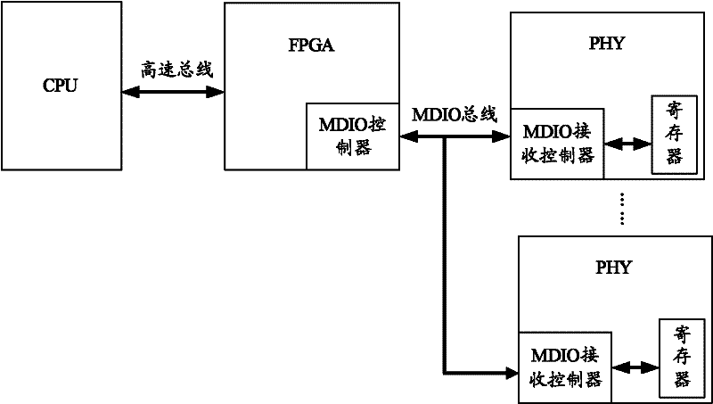
[0004] In the process of realizing the present invention, the inventor found that the prior art has at least the following deficiencies: the solution based on the MAC chip is usually limited by the MAC chip, and it is impossible to use one MDIO controller to control multiple PHY chips at the same time
Although the solution based on FPGA can use one MDIO controller to control multiple PHY chips at the same time, the control process of each PHY chip requires the CPU to set the corresponding registers and control the access timing. Therefore, when multiple PHY chips are frequently controlled When the CPU is required to work non-stop, it will increase the burden on the CPU

Method used


Image

  • Method and control circuit for controlling physical layer chip
  • Method and control circuit for controlling physical layer chip
  • Method and control circuit for controlling physical layer chip

Examples


Embodiment Construction

[0029] In order to make the purpose, technical solutions and advantages of the embodiments of the present invention clearer, the technical solutions in the embodiments of the present invention will be clearly and completely described below in conjunction with the drawings in the embodiments of the present invention. Obviously, the described embodiments It is a part of embodiments of the present invention, but not all embodiments. Based on the embodiments of the present invention, all other embodiments obtained by persons of ordinary skill in the art without creative efforts fall within the protection scope of the present invention.

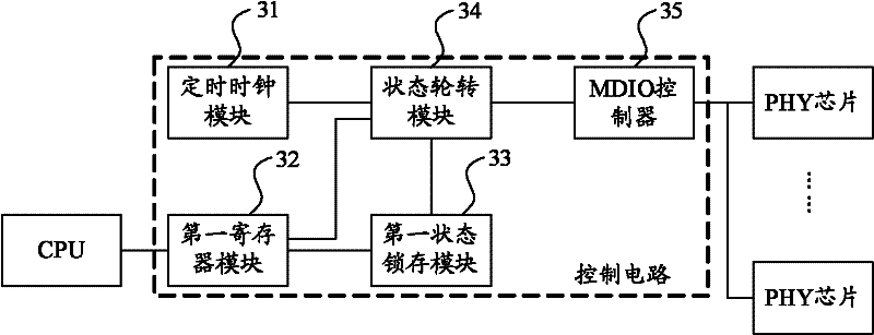
[0030] image 3 It is a schematic structural diagram of the control circuit provided by Embodiment 1 of the present invention. like image 3 As shown, the control circuit of this embodiment includes: a timing clock module 31 , a first register module 32 , a first state latch module 33 , a state rotation module 34 and an MDIO controller 35 .

[...


PUM


Abstract

The invention provides a method for controlling a physical layer (PHY) chip and a control circuit. The control circuit comprises a timing clock module, a first register module, a first state locking and storing module, a state rotation module and a management data input / output (MDIO) controller, wherein the state rotation module is used for reading the first register module according to a clock signal provided by the timing clock module and change information provided by the first state locking and storing module and providing first address information and control data information for the MDIO controller according to a reading result; and the MDIO controller is used for writing the control data information into a register of a pin of the PHY chip corresponding to the first address information so that the pin state of the PHY chip can be controlled automatically. After the technical scheme disclosed by the invention is adopted, the same MDIO controller can be used for managing multiplePHY chips so that the load of a central processing unit (CPU) is reduced.

Description

technical field [0001] The invention relates to communication technology, in particular to a method and a control circuit for controlling a physical layer chip. Background technique [0002] Existing large-scale network equipment usually adopts the General Purpose Input / Output (General Purpose Input / Output; referred to as: MDIO) bus to the physical layer (Physical Layer; : GPIO) pins to control some peripheral devices (such as light-emitting diodes) of the PHY chip. The MDIO bus is defined by the IEEE through several clauses of the Ethernet standard IEEE 802.3. The MDIO bus connects the management device (such as a microprocessor) with the PHY chip, so that the management device controls the PHY chip and collects status information from the PHY chip. [0003] There are two existing solutions for controlling the GPIO pins of the PHY chip based on the MDIO bus, namely a solution based on a Media Access Control (Media Access Control; MAC for short) chip and a solution based o...

Claims


Application Information

Patent Timeline
IPC IPC(8): H04L29/08H04L29/12
Inventor 陈坚
Owner RUIJIE NETWORKS CO LTD
Learn More