
Electronic bug killer with dislocated power grid labyrinth

A technology of insecticide and electronic controller, which is applied to the device, application, and animal husbandry of catching or killing insects. It can solve the problems of frequent short-circuit accidents in the power grid, inability to kill small pests, and failure to use normally, so as to eliminate Power grid short-circuit accident, ingenious structure, and the effect of increasing service life

Active Publication Date: 2013-01-09
湖南伟达塑胶制品有限公司
View PDF5 Cites 0 Cited by
  • Summary
  • Abstract
  • Description
  • Claims
  • Application Information

AI Technical Summary

Problems solved by technology

Its advantage is that it can kill all kinds of flying insects, big and small. The disadvantage is that the vertical line on the positive grid is easy to touch the horizontal line on the negative grid, and the grid is damaged.
Some electronic insecticides set the distance between the positive and negative grids to 10 mm, although it can reduce the occurrence of grid short-circuit accidents, it cannot kill small pests
Especially for electronic insecticides with a drum-shaped grid, the flying insects will fly away from the periphery of the drum while flying around the drum, and the insecticidal effect is poor.

Method used


Image

  • Electronic bug killer with dislocated power grid labyrinth
  • Electronic bug killer with dislocated power grid labyrinth
  • Electronic bug killer with dislocated power grid labyrinth

Examples


Embodiment 1

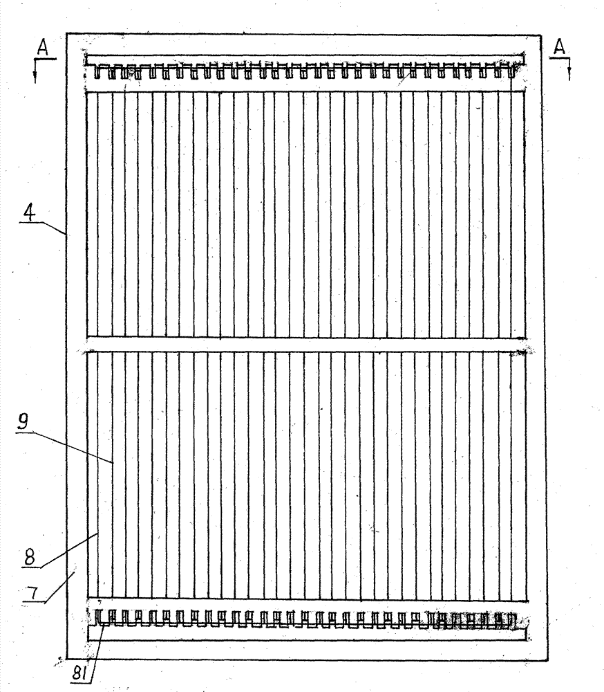
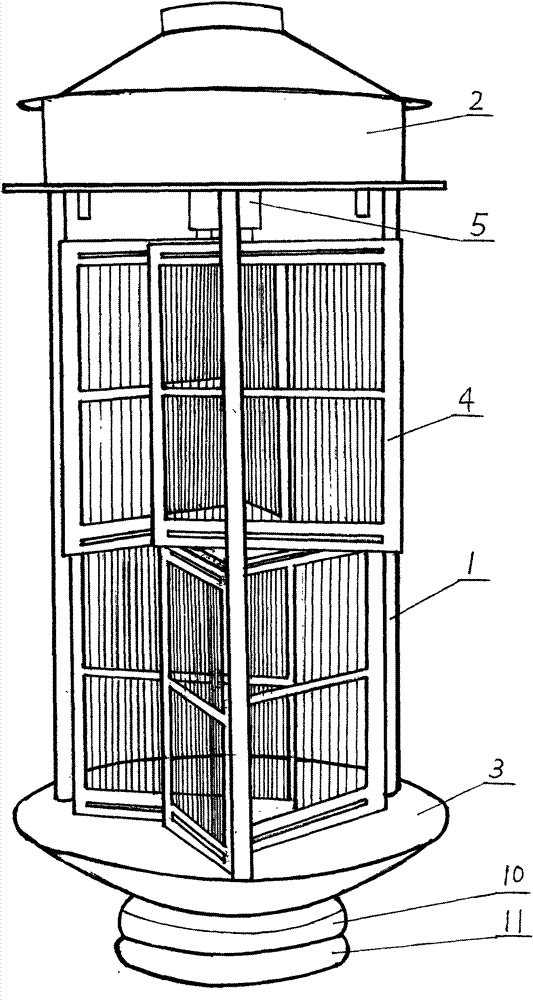
[0021] As shown in the figure, the present invention includes an electronic controller 2 and an insect collection basin 3 respectively installed on the upper and lower ends of the support rod 1. 4 forms the grid labyrinth, and the electronic controller 2 lower center has the lamp holder 5 that is driven by the low-speed motor, and black and white fluorescent lamp tubes are housed on the lamp holder 5. The structure of the grid maze is that three non-adjacent frames of the hexagonal hollow connection frame 6 are respectively connected with an electronic grid board 4 (three grid board type for short, the same below), and the upper and lower layers of the grid labyrinth are dislocated Stack. Described electronic grid board 4 comprises screen frame 7, positive grid 8 and negative grid 9, and the vertical lines of positive grid and negative grid 8, 9 are respectively misplaced and inlaid on grid frame 7, and the vertical lines of positive grid 8 both ends go to the grid. Frame 7 b...

Embodiment 2

[0023] The present embodiment is basically the same as Example 1, except that the structure of the electronic labyrinth is that each frame of the quadrilateral hollow connection frame 6' is connected with an electronic screen 4 (abbreviated as the four-screen type, hereinafter the same).

Embodiment 3

[0025] This embodiment is basically the same as Example 1 or Example 2, except that there are three layers of electronic labyrinths stacked in dislocation.


PUM


Abstract

The invention discloses an electronic bug killer with a dislocated power grid labyrinth. The electronic bug killer is provided with at least one layer of power grid labyrinth comprising electronic mesh plates, wherein a lamp holder driven by a motor is arranged at the center below an electronic controller; and a black fluorescent tube and a white fluorescent tube are arranged on the lamp holder. The power grid labyrinth has the structure that three frames which are not adjacent in a hexagonal hollow connecting framework are respectively connected with one electronic mesh plate, or each frame of a quadrilateral hollow connecting framework is connected with one electronic mesh plate respectively; and more than one layer of power grid labyrinth is overlapped in dislocated manner. The electronic mesh plate comprises a mesh frame, a positive power grid and a negative power grid; and vertical lines of the positive power grid and the negative power grid are respectively dislocated and embedded on the mesh frame. The distance between a plane where the vertical line of the positive power grid is positioned and a plane where the vertical line of the negative power grid is positioned is 3-4mm. The electronic bug killer has the advantages of ingenious structure, prevention of power grid short-circuit accidents, long service life, high killing efficiency, capability of killing large and small pests, wide application range, simpleness and convenience in operation, low use cost, energy saving and environment friendliness.

Description

technical field [0001] The invention relates to an appliance for killing pests by electric shock. Background technique [0002] Various pests bring great harm to human life, especially mosquitoes, cockroaches and various pests that affect the growth of crops. The main method of killing these pests at present is to adopt medicine or poisonous chemical preparation to spray and kill. However, the residues of drugs or toxic chemical trials will pollute the environment and affect water and air quality, especially the residues on food, fruits, and vegetables will seriously affect people's health. In order to avoid the use of drugs or toxic chemicals, physical methods of killing insects using non-toxic substances are becoming more and more important. In addition, the resistance of pests is getting stronger and stronger, pesticides are expensive, there are many empty lawns and weed wastelands, and the breeding areas of pests are wide, and the use of pesticides to control pests can...

Claims


Application Information

Patent Timeline
Patent Type & Authority Patents(China)
IPC IPC(8): A01M1/04A01M1/22
Inventor 胡道德
Owner 湖南伟达塑胶制品有限公司
Learn More