
Alignment stage

A technology of alignment table and table top, applied in the field of alignment table, can solve problems such as thermal deformation and position deviation, and achieve the effect of improving rigidity

Inactive Publication Date: 2011-11-30
IHI CORP
View PDF6 Cites 4 Cited by
  • Summary
  • Abstract
  • Description
  • Claims
  • Application Information

AI Technical Summary

Problems solved by technology

Therefore, thermal deformation may occur on the table 4 and the base 1 due to the influence of heat generated by each servo motor 10, and the unillustrated parts held on the table 4 may be caused by the thermal deformation of the table 4 or the base 1. A positional deviation occurs on the workpiece
[0027] In this way, in Figure 8 and Figure 9 In the conventional alignment table shown above, it is difficult to hold the workpiece on which a moving load is applied in a state where high-precision positioning is performed in the three-axis directions of X, Y, and θ, or to hold the workpiece in a state where a moving load is applied. High-precision position correction in the 3-axis directions of X, Y, and θ

Method used


Image

  • Alignment stage
  • Alignment stage
  • Alignment stage

Examples


Embodiment Construction

[0073] Hereinafter, embodiments for carrying out the present invention will be described with reference to the drawings.

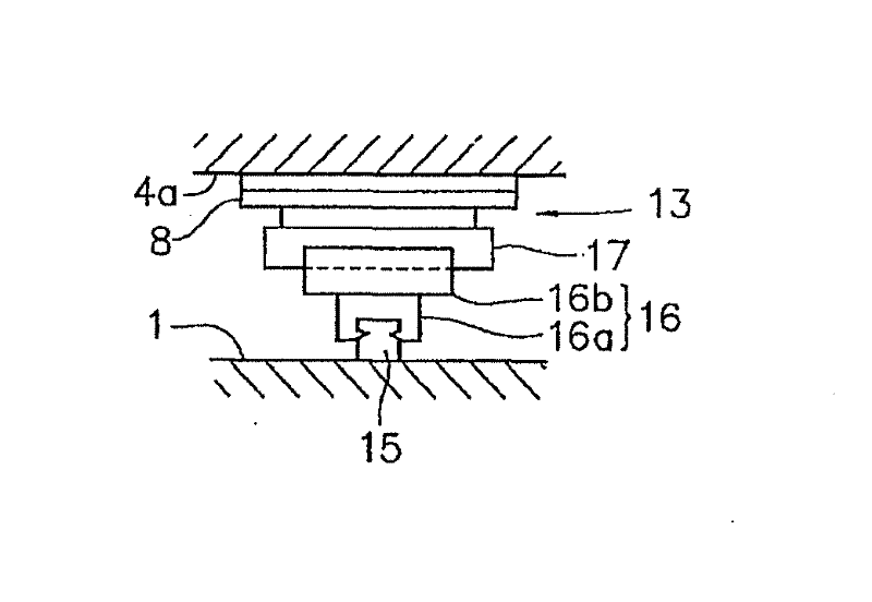
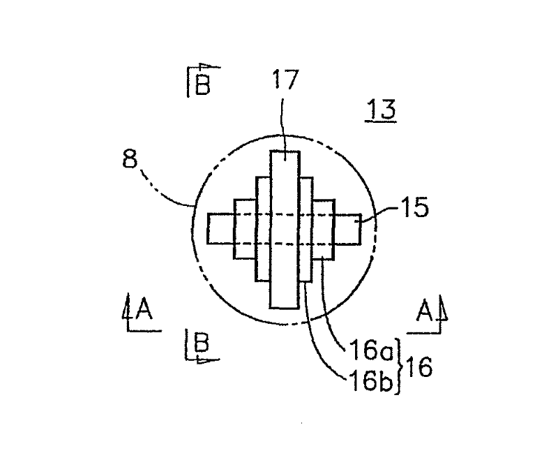
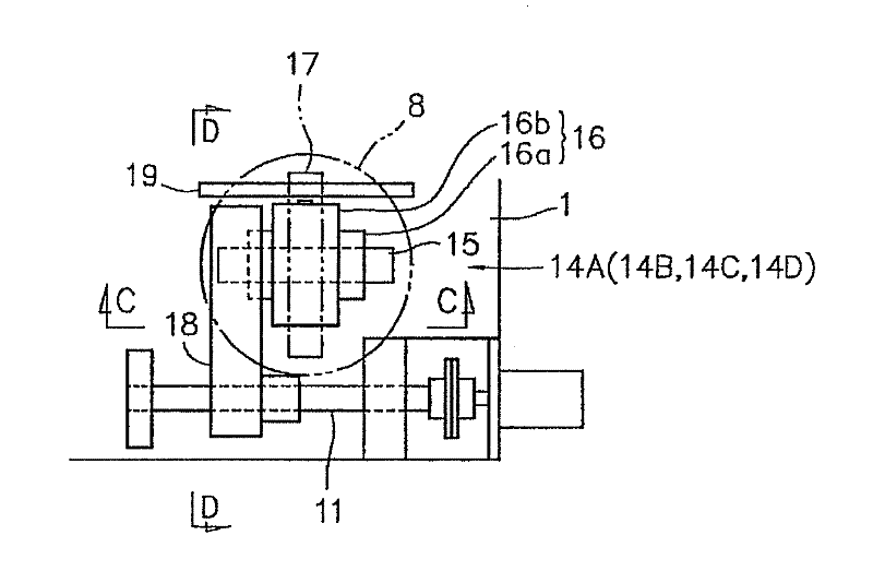
[0074] exist Figure 1 to Figure 5 One embodiment of the alignment stage of this invention is shown in .

[0075] The table top 4a is arranged above the required size of the base 1 as the fixed side. The table top 4 a holds a workpiece (not shown) to which a moving load acts, for example, a plate or a printing object to which a moving load acts by moving a rotating squeegee while pushing against it during offset printing. Between the above-mentioned base 1 and the table 4a, the moving direction of the moving load (hereinafter referred to simply as the load moving direction) acting on the workpiece not shown in the above-mentioned figure is indicated by an arrow L in the figure. Image 6 , Figure 7 The same is true in ) where the required parts are arranged in a staggered manner, for example, from the upstream side of the load moving direction L, in the...


PUM


Abstract

In an alignment stage, a top table 4a, which holds a work piece on which a moving load acts, is disposed above a base 1, and a supporting unit 13 each having three degrees of freedom of X, Y, and θ and driving units 14A, 14B, 14C, and 14D, each having a one-axis direction ball screw linear motion mechanism 9 in addition to the same configuration as that of the supporting unit 13, are interposed between the base 1 and the top table 4a to be disposed at locations corresponding to the center and four corner portions of the top table 4a, which are disposed in a zigzag fashion in a load movement direction L. The ball screw linear motion mechanisms 9 of the driving units 14A and 14B of diagonal positions on one side and the ball screw linear motion mechanisms 9 of the driving units 14C and 14D of diagonal positions on the other side are disposed to be at right angles to each other. A moving load which acts on the top table 4a through a work piece while moving in the load movement direction L is continuously received by the respective driving units 14A and 14C, the supporting unit 13, and the respective driving units 14B and 14D, so that deformation of the top table 4a is suppressed.

Description

technical field [0001] The present invention relates to an alignment table, and more particularly to an alignment table provided with three degrees of freedom of X, Y, and θ for aligning a workpiece receiving a moving load. [0002] This application claims priority based on Japanese Patent Application No. 2009-126034 for which it applied in Japan on May 26, 2009, and uses the content here. Background technique [0003] In recent years, as a method of forming electrode patterns (conductive patterns) such as liquid crystal displays on required substrates, printing techniques using conductive pastes as printing inks, For example, a method of printing and forming an electrode pattern on a substrate using a gravure offset printing technique (for example, refer to Patent Document 1 and Patent Document 2). [0004] When offset printing a fine printing pattern such as the above-mentioned electrode pattern on a flat plate-shaped printing object such as the above-mentioned substrate,...

Claims


Application Information

Patent Timeline
Patent Type & Authority Applications(China)
IPC IPC(8): B41F33/14B23Q1/48B41F15/16B41F17/14B65G49/06G02F1/13G05D3/00H01L21/68
CPCB41F3/51H01L21/68B65G2249/02B65G49/061B41F33/14B23Q1/48B41F15/16B65G49/06
Inventor 斎藤浩
Owner IHI CORP
Learn More