
Flapping wing flight adopting compound flapping mode

A flapping-wing aircraft and driving mechanism technology, applied in the field of flapping-wing aircraft, can solve the problems of low reliability and large empty weight of the flapping-wing aircraft, and achieve the effects of small lift resistance and high aerodynamic efficiency

Inactive Publication Date: 2013-04-24
NORTHWESTERN POLYTECHNICAL UNIV
View PDF6 Cites 0 Cited by
  • Summary
  • Abstract
  • Description
  • Claims
  • Application Information

AI Technical Summary

Problems solved by technology

[0008] In order to overcome the deficiencies in the prior art of complex mechanism, high empty weight and low reliability of the flapping-wing aircraft, the present invention provides a flapping-wing aircraft that can be used as the aircraft platform of the miniature flapping-wing unmanned aerial vehicle system, so that the entire aircraft has a high aerodynamic Efficiency, meeting the load and space requirements of the UAV system, while being simple to control and reliable to use

Method used


Image

  • Flapping wing flight adopting compound flapping mode
  • Flapping wing flight adopting compound flapping mode
  • Flapping wing flight adopting compound flapping mode

Examples


Embodiment Construction

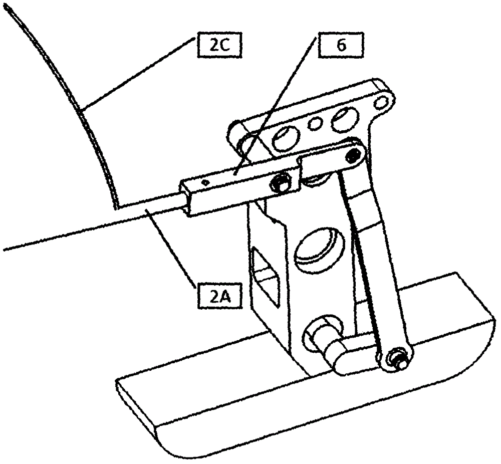
[0028]The composite flapping-wing aircraft of the present invention comprises a fuselage, a flapping wing and an empennage, and the fuselage is a composite material thin shell structure in the form of a cabin body, made of a glass fiber resin-based composite material or a carbon fiber resin-based composite material , left and right symmetrical, divided into nose 1A and body 1B.

[0029] There is at least one supporting frame inside the body 1B for fixing the flapping wing drive mechanism. If the number of the supporting frame is more than one, except for the supporting frame that fixes the flapping wing drive mechanism, the remaining supporting frames play a supporting role in the body, and are arranged in the following locking device, steering gear installation position and empennage Positions where concentrated loads such as fixed positions act. The front part of the airframe 1B has a straight section with a rounded rectangle in cross section, where the flight control and n...


PUM


Abstract

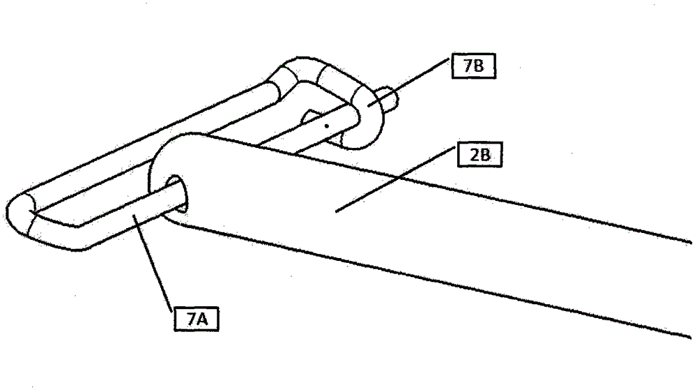
The invention discloses a flapping wing flight adopting a compound flapping mode. The flapping wing flight comprises a flight body, flapping wings and a tail fin. The rotation of a rotary power device is converted into vertical reciprocating flapping motions of a rocker arm by a flapping wing drive mechanism; each flapping wing comprises a main beam on the front edge and an auxiliary beam behind the main beam; the root of the main beam is connected with a blind hole in the rocker arm of the flapping wing drive mechanism in an inserting manner; the root of the auxiliary beam is hinged with a locking device on the flight body; a limiting rod fixedly connected to the flight body is clamped into a locker fixedly connected to the flight body after penetrating a connecting hole in the root of the auxiliary beam of the flapping wing in a manner of being parallel to a symmetrical plane of the flight body; and the length of the limiting rod can ensure that the connecting hole of the auxiliary beam of the flapping wing is driven to move forwards and backwards on the limiting rod along the vertical flapping motions of the flapping wing without being interfered by the motion of the locking device in the flapping process of the flapping wings. The invention has the advantages of high aerodynamic efficiency, large effective load and interior space and good dynamics performance under all kinds of typical flight modes.

Description

technical field [0001] The invention relates to a flapping-wing aircraft, in particular to a miniature flapping-wing aircraft. Background technique [0002] The micro flapping wing aircraft is a new concept aircraft that imitates the flight of birds. It has the advantages of small size, light weight, flexible use, and high efficiency. If it is equipped with sensors and related data transmission and flight control systems, it will form a micro flapping wing unmanned machine platform, it will have broad application prospects. Around this subject, countries have developed controllable flying flapping-wing aircraft, among which the more successful ones are "Microbat" jointly developed by Aero Vironment of the United States and the University of California, and "Delfly" of Delft University in the Netherlands. However, these flapping-wing aircraft are far from The aircraft platforms of the practical UAV system have a certain distance. [0003] The main reason why the micro flapp...

Claims


Application Information

Patent Timeline
Patent Type & Authority Patents(China)
IPC IPC(8): B64C33/00B64C33/02
Inventor 王进宋笔锋王利光李洋杨文青高广林付鹏
Owner NORTHWESTERN POLYTECHNICAL UNIV
Learn More