
Method for manufacturing steel-aluminum composite conductor rail

A steel-aluminum composite and manufacturing method technology, applied in the field of conductive rails, can solve the problems of stainless steel strips not tightly bonded, high investment in production equipment, complicated preparation methods, etc., and achieve high production efficiency, low manufacturing difficulty, and good wear resistance Effect

Inactive Publication Date: 2013-01-09
SHANGHAI SANY PRECISION MACHINERY
View PDF3 Cites 0 Cited by
  • Summary
  • Abstract
  • Description
  • Claims
  • Application Information

AI Technical Summary

Problems solved by technology

[0008] 1) The combination between the stainless steel strip and the aluminum rail is not tight, and a gap is easily formed, resulting in an increase in contact resistance;
[0009] 2) The preparation method is complex, difficult, low yield and low production efficiency;
[0010] 3) High investment in production equipment and high production costs;
[0011] 4) After the conductor rail is formed, it is easy to deform due to vibration and other factors, and the life of the conductor rail is low

Method used


Image

  • Method for manufacturing steel-aluminum composite conductor rail
  • Method for manufacturing steel-aluminum composite conductor rail
  • Method for manufacturing steel-aluminum composite conductor rail

Examples


Embodiment Construction

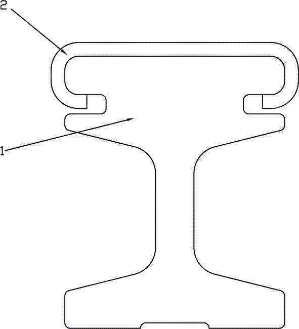
[0041] see Figure 1 to Figure 4 , the manufacturing method of steel-aluminum composite conductor rail, it comprises the steps:

[0042] a. Preparation of aluminum rail 1

[0043] The aluminum billet is hot-extruded through an extrusion machine to form an I-shaped aluminum rail 1. Grooves 11 and 12 are formed on both sides of the upper end of the aluminum rail, and the notches of the grooves are arc-shaped.

[0044] b. Prefabricated C-shaped stainless steel belt 2

[0045] The stainless steel coil is cut into long stainless steel strips, cold-bending and rolling on cold-bending equipment, and rolled by multiple rolling dies to form a C-shaped stainless steel strip 2, which includes a base 21 and extends from the base 21 to both sides. And bend down to form the first bending part 22, 22', extend from the first bending part 22, 22' and bend inward to form the second bending part 23, 23', extend from the second bending part to form a hook Part 24, 24'; after the rolling is com...


PUM


Abstract

The invention discloses a method for manufacturing a steel-aluminum composite conductor rail, comprising the following steps of: a) preparing an aluminum rail: preparing an I-shaped aluminum rail by a mould through hot extrusion molding, wherein the two side surfaces of the upper end of the aluminum rail are provided with grooves; b) prefabricating a C-shaped stainless steel strip: cutting a stainless steel coil into stripy stainless steel strips, and cold bending and rolling by a cold bending unit to form a stainless steel strip with a C-shaped section, wherein the formed stainless steel strip comprises a base part, a first bending part, a second bending part and a clip part, the first bending part is formed by extending from the two sides of the base part and bending downwards, the second bending part is formed by extending from the first bending part and bending inwards, and the clip part is formed by extending from the second bending part; and c), compounding the C-shaped stainless steel strip and the aluminum rail, wherein the clip parts at two ends of the C-shaped stainless steel strip are embedded in the grooves on the two sides of the upper end of the aluminum rail, and the C-shaped stainless steel strip is completely attached to the upper part of the aluminum rail. According to the method in the invention, the stainless steel strip and the aluminum rail are closely combined, the combined surface is large, the transition resistance is small, deformation is not liable to occur after forming, a local heating mode is adopted during rolling compounding to facilitate forming, machining is not needed after rolling forming, and the production efficiency is greatly improved.

Description

technical field [0001] The invention relates to conductive rail technology, in particular to a manufacturing method of a steel-aluminum composite conductive rail. Background technique [0002] With the development of the times, in order to reduce current loss, increase the primary transmission distance of the conductor rail, reduce mechanical wear and electrical corrosion, and improve economic and social benefits, a new type of conductor rail—steel rail—appeared in the late 1970s. Aluminum composite conductor rail. It is widely used at home and abroad because of its good electrical conductivity, large current capacity, light weight, easy installation, good wear resistance and corrosion resistance, and long service life. [0003] In this case, the composite form of steel and aluminum determines the performance of the conductor rail. The existing steel-aluminum composite forms in this field include riveting type, welding type and co-extrusion type. [0004] The "steel-alumi...

Claims


Application Information

Patent Timeline
Patent Type & Authority Patents(China)
IPC IPC(8): B21D39/00
Inventor 汪强华王俊平庄超煌
Owner SHANGHAI SANY PRECISION MACHINERY
Learn More