
An antenna device for a radio communication device

A technology for an antenna device and a display device, which is applied in the directions of electrical short antennas, components of lighting devices, and independent antenna unit combinations, etc., can solve problems such as limiting antenna design.

Inactive Publication Date: 2011-11-16
LAIRD TECH INC
View PDF3 Cites 14 Cited by
  • Summary
  • Abstract
  • Description
  • Claims
  • Application Information

AI Technical Summary

Problems solved by technology

This further limits the design of portable radio communication device antennas

Method used


Image

  • An antenna device for a radio communication device
  • An antenna device for a radio communication device
  • An antenna device for a radio communication device

Examples


Embodiment Construction

[0049] In the following description, for purposes of explanation rather than limitation, specific details are set forth, such as particular techniques and applications, in order to provide a thorough understanding of the present invention. It will be apparent, however, to one skilled in the art that the invention may be practiced in other embodiments that depart from these specific details. In other instances, detailed descriptions of known methods and apparatuses may be omitted so as not to obscure the description of the present invention with unnecessary detail.

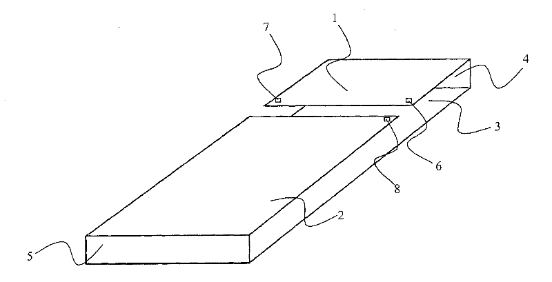
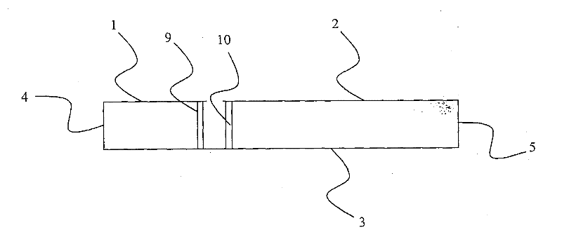
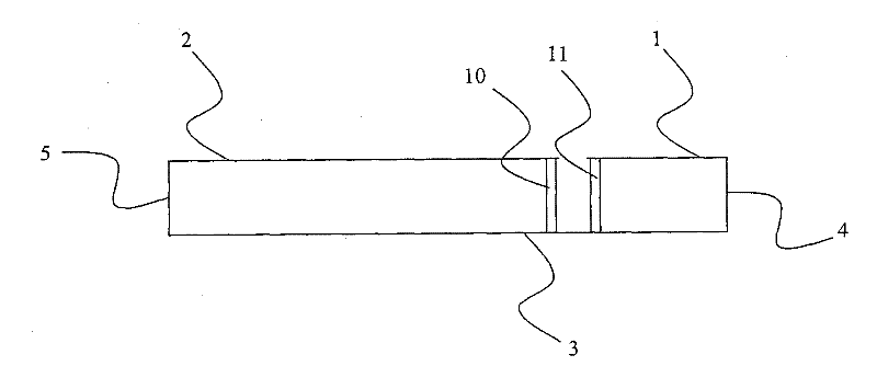
[0050] Now, refer to Figure 1-3 An antenna device for a portable radio communication device according to a first embodiment of the present invention will be described.

[0051] The antenna arrangement comprises a metal cover of a portable radio communication device (here described as a mobile phone). The rear side of the metal cover arranged on the rear side of the mobile phone is divided into two parts. The fi...


PUM


Abstract

The present invention relates to an antenna device for a portable radio communication device. The antenna device comprises a metal front side part (3), a first metal back side part (1) electrically connected to the front side part through a metal top side part (4), a second metal back side part (2) electrically connected to the front side part through a metal bottom side part (5), wherein the bottom and top side parts are positioned at opposite ends of the front side part, and the first and second back side parts are positioned essentially coplanar and distanced from each other by a slot, and the front side part electromagnetically screens the antenna device from a display means (37) of the portable radio communication device.

Description

field of invention [0001] The present invention relates generally to antenna devices for radio communication devices, and more particularly to antenna devices for portable radio communication devices. Background technique [0002] For portable radio communication devices (eg mobile phones, PDAs, portable computers, etc.), the current trend is to provide devices with metal covers. Since the metal cover of the portable radio communication device shields the interior of the device with respect to radio frequencies, the metal cover makes it difficult to provide the portable radio communication device with a non-extruding antenna. Only a portion of the cover may be provided as a metal cover to allow use of the internal antenna, but it is still desirable to provide a full metal cover. [0003] For portable radio communication devices such as mobile phones etc., another trend is to provide devices with very wideband coverage, eg covering GSM850, GSM900, GSM1800, GSM1900, UMTS 2100...

Claims


Application Information

Patent Timeline
Patent Type & Authority Applications(China)
IPC IPC(8): H01Q1/22H01Q1/36H01Q1/52H04M1/02H01Q5/40H01Q5/50
CPCH01Q5/0072H01Q21/28H01Q21/30H01Q9/0421H01Q5/0093H01Q1/526H01Q1/243H01Q5/40H01Q5/50F21V5/045F21V5/007F21V5/008G02B3/02F21W2111/043F21Y2115/10Y10S362/80
Inventor 阿克塞尔·冯·阿尔宾乌尔夫·帕林佩尔·艾尔兰德森
Owner LAIRD TECH INC
Learn More