Eureka AIR delivers breakthrough ideas for toughest innovation challenges, trusted by R&D personnel around the world.

Temperature drift compensation method for gyroscope

A temperature drift and compensation method technology, applied in the field of human-computer interaction, can solve the problems of difficulty, the calibration system is not simple enough, and the zero drift problem of the gyroscope is not paid attention to, so as to achieve the effect of correcting data errors, simple data conversion, and avoiding adverse effects

Active Publication Date: 2011-11-02
INST OF SOFTWARE - CHINESE ACAD OF SCI
View PDF10 Cites 41 Cited by
  • Summary
  • Abstract
  • Description
  • Claims
  • Application Information

AI Technical Summary

Problems solved by technology

[0006] [Second, the optimal position calibration method of the static drift zero-order and first-order acceleration-related item error model of the flexible gyroscope is mainly oriented to the static drift error caused by linear motion, but does not pay attention to the zero-point drift of the gyroscope caused by temperature
[0007] Third, for users in the field of human-computer interaction who are not familiar with gyroscopes and do not have related calibration equipment, the calibration system of fiber optic gyroscopes is not simple enough, and there are difficulties in actual use.

Method used


Image

  • Temperature drift compensation method for gyroscope
  • Temperature drift compensation method for gyroscope
  • Temperature drift compensation method for gyroscope

Examples


Embodiment Construction

[0038] In order to enable those skilled in the art to better understand the present invention, the present invention will be further described in detail below in conjunction with the accompanying drawings and embodiments.

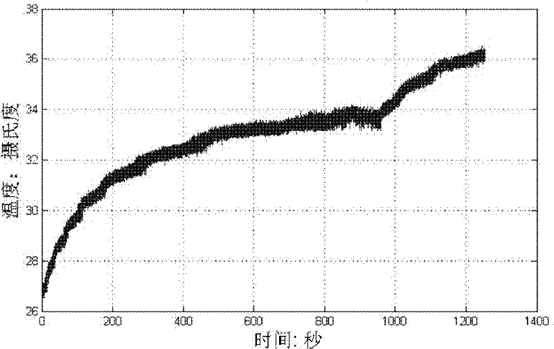
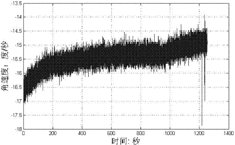
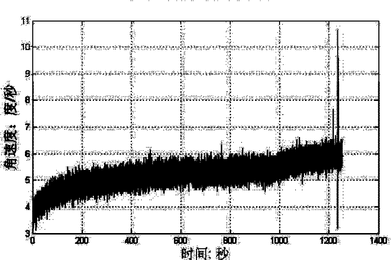
[0039] For a brand-new gyroscope sensor device, in order to obtain the curve of the zero point of the gyroscope with temperature, we need to collect a series of data, including temperature and the three axes of the gyroscope, under the premise that the gyroscope is in a static state and only the temperature changes. The unit of temperature is generally degrees, and the unit of gyroscope output data is degrees per second or radians per second. In order to avoid accidental errors, it is necessary to make these data distributed in as large a temperature range as possible, and to measure multiple times to reduce measurement errors. Since the temperature change of the gyro sensor cannot be precisely controlled, the original data cannot be equally distributed on ...


PUM


Abstract

The invention provides a temperature drift compensation method for gyroscope. The method comprises the following steps: 1) collecting temperatures of the gyroscope and angular velocity data of three axis of the gyroscope under a stable state; 2) carrying out sorting according to the temperatures to divide the temperatures into a plurality of intervals with a equal interval; 3) carrying out equivalent sampling for the angular velocity data within the intervals; 4) calculating arithmetic means for the sampled angular velocity data in each temperature interval, and adopting the arithmetic means as angular velocity representative values; 5) carrying out linear fitting for numerical value pairs of the temperature and the zero angular velocity through a linear fitting formula of y=a+bx to obtain values of a parameter a and a parameter b, wherein the x represents the temperature, the y represents the zero value; 6) measuring the angular velocity values and the temperature values of the three axis of the current gyroscope, and calculating the zero value through the linear fitting formula, then subtracting the zero value from the measured angular velocity values to complete the temperature drift compensation of the gyroscope. The method is applicable for a temperature drift compensation correction condition of general gyroscopes and can provides a compensation factor without a plurality of tests and emulations, and is simple and available.

Description

technical field [0001] The invention belongs to the field of human-computer interaction, and in particular relates to a temperature drift compensation method of a gyroscope. Background technique [0002] Since the first practical gyroscope came out more than half a century ago, it has been widely used in many fields such as navigation, aviation and aerospace. As a sensitive inertial navigation component, it is usually designed as a gyroscope sensor in the civilian field to provide us with information such as direction and position. [0003] However, there are certain problems in the use of gyroscopes, for example, the zero point of the gyroscope axis angle will drift with changes in temperature and motion. Among them, the influence of temperature is particularly obvious. On the one hand, the ambient temperature is constantly changing slightly. On the other hand, as the use time of the three-axis gyroscope sensor increases, its temperature is also rising continuously, and i...

Claims


Application Information

Patent Timeline
IPC IPC(8): G01C25/00G01C19/00
Inventor 田丰罗文灿王宏安
Owner INST OF SOFTWARE - CHINESE ACAD OF SCI
Why Eureka
Eureka Blog
Learn More