
Low concentration photovoltaic generating module

A technology of concentrating photovoltaics and power generation modules, applied in the field of solar photovoltaics, can solve the problems of reducing the use effect and life of the system, reducing the cost of the original intention, and unfavorable for the normal operation of the cells, so as to avoid daily tracking and macular effect , reliable performance

Inactive Publication Date: 2011-10-19
广西天洋机电设备有限公司 +1
View PDF5 Cites 5 Cited by
  • Summary
  • Abstract
  • Description
  • Claims
  • Application Information

AI Technical Summary

Problems solved by technology

Although the tracking technology and cooling technology are mature, the manufacturing, operation, and maintenance costs of the equipment are relatively high, accounting for more than 30% of the total system cost, thus defeating the original intention of reducing power generation costs through concentrating technology
In addition, the uniformity of light intensity distribution of this concentrated spot is poor, which is not conducive to the normal operation of the cell
[0005] Some concentrating power generation systems use reflective bucket-type concentrating devices, which are suitable for low-power concentrating systems. Although water cooling systems are omitted and the disadvantages of poor uniformity of light intensity distribution are avoided, due to their low concentrating efficiency, The light concentration ratio design of more than ten times can only get about 3 times the light concentration effect in practice, and the light concentration efficiency is less than 10% (the so-called light concentration efficiency here refers to the light energy irradiated on the silicon cell and the incident light energy ratio)
Some concentrating power generation systems need to set up another tracking system, which results in the original intention of cost reduction being greatly compromised
In addition, because the outer surface of the glass plate of the existing concentrating power generation system is not protected, the light transmittance will decrease due to natural erosion in 3-5 years, reducing the use effect and life of the system

Method used


Image

  • Low concentration photovoltaic generating module
  • Low concentration photovoltaic generating module
  • Low concentration photovoltaic generating module

Examples


Embodiment Construction

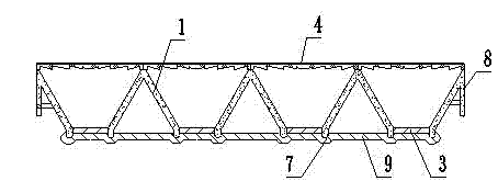
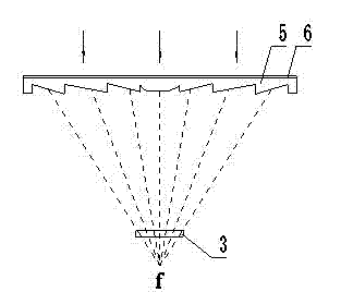
[0024] Referring to the accompanying drawings, the present invention coats the outer surface of the glass or transparent resin substrate 5 of the component module with an optical film 6 to make a coated transparent cover plate 4, and the optical film 6 is a composite optical film.

[0025] The glass or transparent resin substrate 5 has a thickness of 2.8 to 5 mm. Silicon dioxide (SiO2), titanium dioxide (TiO2), zirconium dioxide (ZrO2), aluminum oxide (Al2O3), and Niobium (Nb2O5), tantalum pentoxide (Ta2O5), and magnesium fluoride (MgF) are used as raw materials, and are plated into single-layer, double-layer, three-layer or multi-layer composite optical dielectric films.

[0026] Appropriate matching and thickness design of these film materials can make the coated transparent cover plate 4 have an anti-reflection effect on the relevant bands of the solar spectrum (0.4-1.1 μm), and different film system designs can obtain different anti-reflection effects; It can block ultrav...


PUM


Abstract

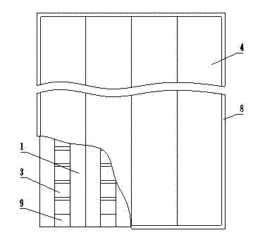
The invention provides a low concentration photovoltaic generating module which comprises solar energy cells, a heat radiation base plate, mirror side concentrators, a plated film transparent cover plate and a frame. The solar energy cells are arranged in rows and adhere to the heat radiation base plate uniformly through a insulation heat conduction bonding layer, and is in series connection to form a cell string through a bus bar. A strip mirror side concentrator with a herringbone cross section is arranged between adjacent two rows of solar energy cells to converge incident light to cells. The plated film transparent cover plate covers the upper part of the mirror side concentrators. The heat radiation base plate, the mirror side concentrator, the plated film transparent cover plate and the frame are hermetically assembled. The invention integrates good points of traditional flat type solar energy photovoltaic cell panel and light collecting solar module, and avoids the shortcomings of them. The low concentration photovoltaic generating module in the invention has the advantages of low cost, reliable performance and convenient use, and sets the stage for the popularization of solar energy generating technology.

Description

technical field [0001] The invention relates to a concentrating solar cell component module, which belongs to the technical field of solar photovoltaic technology. Background technique [0002] With the depletion of global energy and the enhancement of human awareness of environmental protection, the solar power generation business centered on silicon photovoltaic cells has developed rapidly in recent years. At present, there are two main types of solar cell components, namely, traditional flat solar photovoltaic cell panels and concentrating solar cell components. [0003] Traditional flat-panel solar photovoltaic panels generate power under sunlight, using more silicon wafers, and the cost of power generation is high and difficult. The macular effect, which is a headache for the industry, affects the light transmission and even burns out, and it cannot be partially renewed, resulting in the scrapping of the expensive whole module template. In addition, this kind of silic...

Claims


Application Information

Patent Timeline
Patent Type & Authority Applications(China)
IPC IPC(8): H01L31/052H01L31/048H02N6/00H01L31/054H02S40/20
CPCY02B10/10Y02E10/50
Inventor 李国昌杜阿青
Owner 广西天洋机电设备有限公司
Learn More