
Snow removing and melting machine

A snow melting and snow melting technology, applied in snow surface cleaning, construction, cleaning methods, etc., can solve problems such as unfavorable environmental protection, unsafe hazards for pedestrians and vehicles, and methods and equipment for road snow accumulation. Conducive to environmental protection and low cost of use

Inactive Publication Date: 2011-10-12
樊亮伟
View PDF5 Cites 11 Cited by
  • Summary
  • Abstract
  • Description
  • Claims
  • Application Information

AI Technical Summary

Problems solved by technology

[0002] At present, snow accumulation will form in places with more snowfall in winter, especially when there is more snow accumulation on the road surface, it will pose a safety hazard to pedestrians walking or driving vehicles such as bicycles, especially snow accumulation on urban traffic arteries. clean up
However, there are not many methods and equipment for removing snow on the road, and the removal effect is not very satisfactory; for example: throwing sand and snow melting agent to make the road snow in a non-frozen state, and melt it as soon as possible, and drain it from the ditch; there are also bulldozers. The equipment pushes and collects the snow accumulation on one side of the road surface into piles, and then cleans it up, and there is also a snow removal machine that pushes the snow accumulation while melting and discharging it; however, the above-mentioned method and equipment for clearing snow accumulation on the road are not fully suitable for municipal use. Use on the main road
Its disadvantages are: throwing sand and deicing agent is not conducive to environmental protection, and the accumulated water after snow melting will damage roadside flowers, trees and field seedlings, and the cost of throwing a large amount of deicing agent is also relatively high; The excreted snowmelt and accumulated water will form glaciers on the road surface, posing new unsafe hazards to pedestrians and vehicles

Method used


Image

  • Snow removing and melting machine
  • Snow removing and melting machine
  • Snow removing and melting machine

Examples


specific Embodiment approach

[0027] DETAILED DESCRIPTION OF THE PREFERRED EMBODIMENTS The present invention will be further described below in conjunction with the accompanying drawings

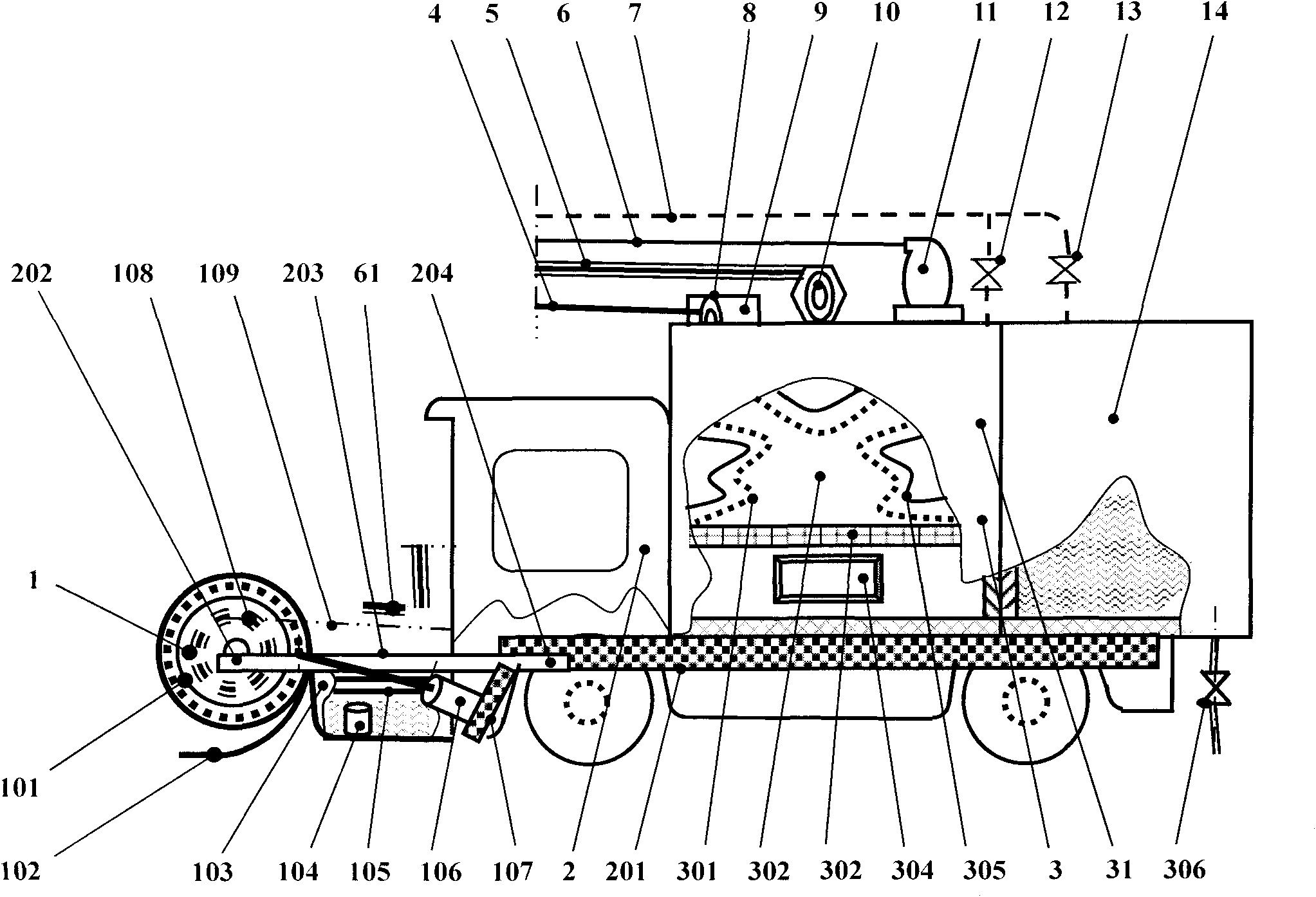
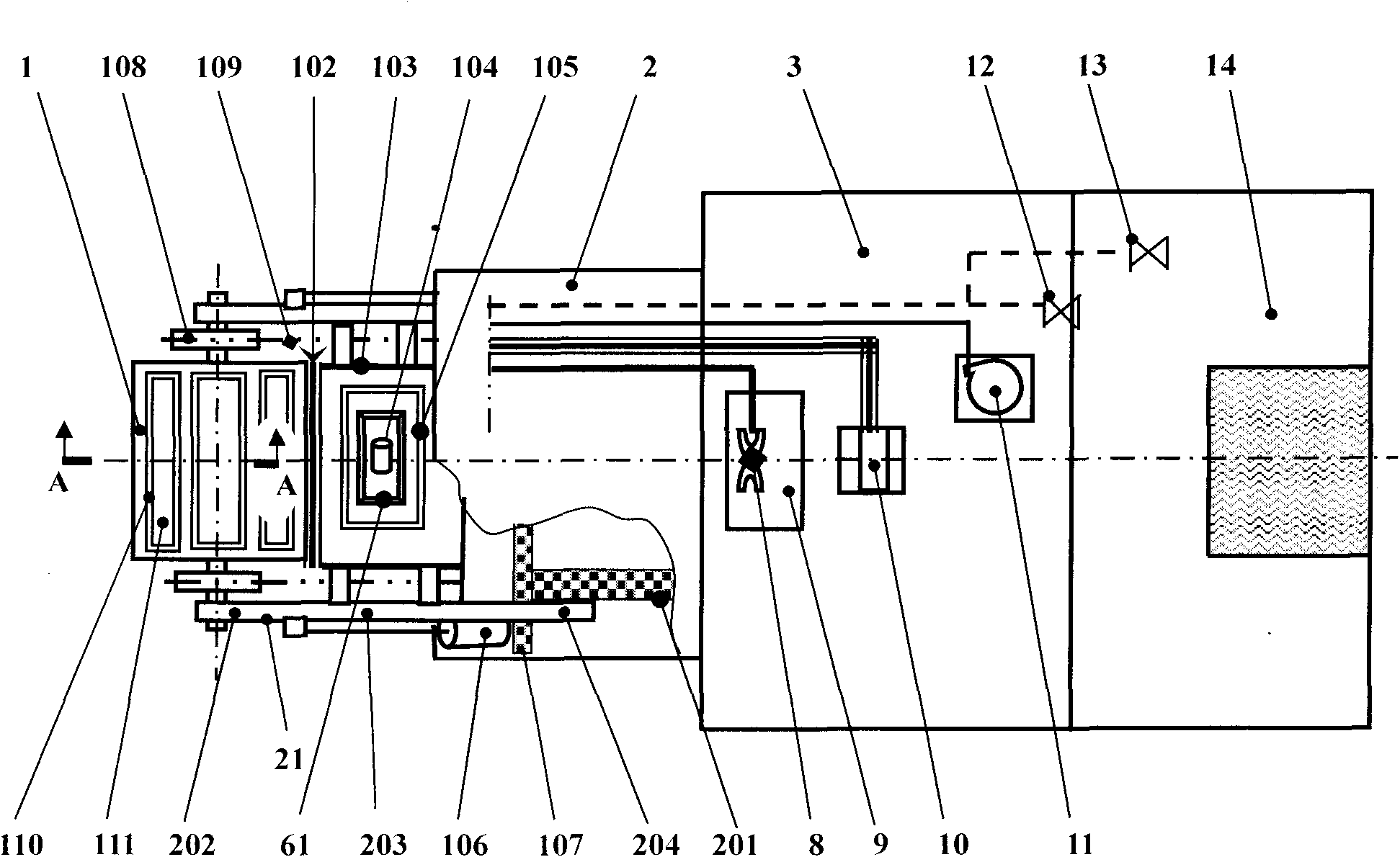
[0028] exist figure 1 , figure 2 , image 3 , Figure 4 , Figure 5 In the shown embodiment, a kind of snow removal and snow-melting machine, it comprises vehicle cab 2, and its characteristic is: the position below the front end of vehicle cab 2 is provided with snow accumulation device 1, the crossbeam steel at the vehicle cab 2 rear end The upper position of the structure 201 is provided with a heating and heat preservation device 3 and an open water collection tank 14;

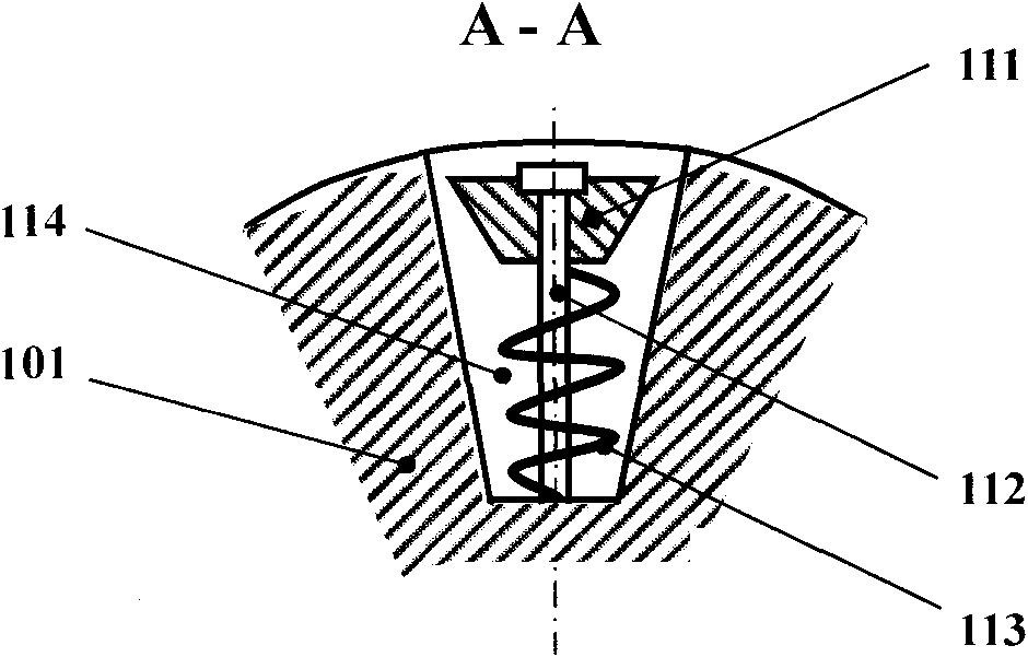
[0029] Described snow accumulating device 1 is made of the snow rolling wheel 101 of cylindrical shape, the snow shovel plate 102 of curved shape, the snowmelt tank 103 of rectangular cavity shape, and its snow rolling wheel 101 is arranged on the front end of snow accumulating device 1, rolls snow. The axle ends on both sides of the wheel end ...


PUM


Abstract

The invention discloses a snow removing and melting machine, belonging to the technical field of mechanical engineering relating to mechanical equipment for removing road snow. The task of the invention is to provide the snow removing and melting machine. The technical scheme is as follows: the snow removing and melting machine comprises a vehicle cab (2), wherein a snow accumulating device (1) is arranged at the lower position of the front end of the vehicle cab (2); and a heating and heat insulating device (3) and an open-type water gathering tank (14) are arranged at the upper position of a beam steel structure (201) on the back end of the vehicle cab (2). When the machine removes the accumulated snow, the drained accumulated snowmelt cannot give rise to a molten ice river on the road surface and new potential safety hazards for pedestrians and vehicles; and the snowmelt cannot damage plants and trees on the roadsides and seedlings in the fields so as to protect the environment; meanwhile, the use cost is lower.

Description

technical field [0001] The invention belongs to the technical field of mechanical engineering, in particular to a mechanical device for clearing road snow. Background technique [0002] At present, snow accumulation will form in places with more snowfall in winter, especially when there is more snow accumulation on the road surface, it will pose a safety hazard to pedestrians walking or driving vehicles such as bicycles, especially snow accumulation on urban traffic arteries. cleared away. However, there are not many methods and equipment for removing snow on the road, and the removal effect is not very satisfactory; for example: throwing sand and snow melting agent to make the road snow in a non-frozen state, and melt it as soon as possible, and drain it from the ditch; there are also bulldozers. The equipment pushes and collects the snow accumulation on one side of the road surface into piles, and then cleans it up, and there is also a snow removal machine that pushes the...

Claims


Application Information

Patent Timeline
Patent Type & Authority Applications(China)
IPC IPC(8): E01H5/10
Inventor 樊亮伟
Owner 樊亮伟
Learn More