Driving method of liquid crystal device

A technology of a liquid crystal display device and a driving method, which can be applied to static indicators, instruments, etc., and can solve problems such as poor display images

Active Publication Date: 2011-09-28
CPT TECH GRP +1
View PDF4 Cites 3 Cited by
  • Summary
  • Abstract
  • Description
  • Claims
  • Application Information

AI Technical Summary

Problems solved by technology

[0011] The purpose of the present invention is to provide a driving method for a liquid crystal display device, which aims to solve the problem of bad display images existing in the prior art when multiple continuous scanning lines are turned on at the same time

Method used


Image

  • Driving method of liquid crystal device
  • Driving method of liquid crystal device
  • Driving method of liquid crystal device

Examples


Embodiment Construction

[0020] In order to make the object, technical solution and beneficial effects of the present invention more clear, the present invention will be further described in detail below in conjunction with the accompanying drawings and embodiments. It should be understood that the specific embodiments described here are only used to explain the present invention, not to limit the present invention.

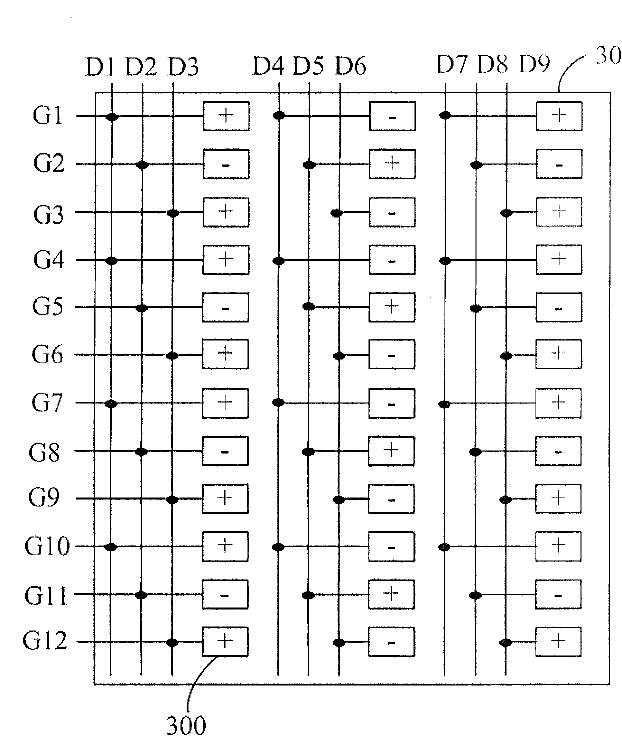
[0021] see image 3 , is a structural diagram of the driving method of the liquid crystal display device 30 provided by the embodiment of the present invention. The liquid crystal display device 30 includes a plurality of scanning lines G1 to G12, a plurality of data lines D1 to D9 and a plurality of pixel units 300, each pixel unit 300 is corresponding to one of the scanning lines G1 to G12 and the data lines D1 to D9 One of the driving methods is to simultaneously turn on multiple scanning lines G1 to G12 to increase the charging time, wherein the turned-on scanning lines are separate...


PUM


Abstract

The invention relates to a driving method of a liquid crystal device. The liquid crystal device comprises a plurality of scanning lines, a plurality of data lines and a plurality of pixel units, wherein each pixel unit corresponds to one scanning line and one data line. The driving method comprises: at least two scanning lines are simultaneously conducted, wherein the at least two scanning lines are separated at an interval of at least one scanning line which is not conducted simultaneously and are different from all the data lines coupled with the at least two scanning lines; and respective image data is transmitted to the data lines coupled with the at least two scanning lines. By utilizing the driving method, the problems of bad display pictures and errors of the display pictures can be solved.

Description

technical field [0001] The present invention relates to a liquid crystal display device, in particular to a driving method of a liquid crystal display device. Background technique [0002] The display area of ​​the liquid crystal display device mainly includes a plurality of scanning lines, a plurality of data lines and a plurality of pixel units arranged in a matrix. Each pixel unit is controlled by a scan line and a data line coupled thereto to display images. All pixel units each have a thin film transistor (Thin Film Transistor; TFT) as a switching element. When a scanning line is turned on, each pixel unit on the scanning line will be connected to its corresponding data line and receive image data. , and each pixel unit will be charged to an appropriate voltage. Then the scanning line is turned into a non-conducting state, and the image data will not be received again until the next time it is turned on, and then the next scanning line is turned on, and the above step...

Claims


Application Information

Patent Timeline
Patent Type & Authority Applications(China)
IPC IPC(8): G09G3/36G02F1/133
Inventor 周焕庭邱显钧李菱陈盈惠戴文智刘家麟莫启能
Owner CPT TECH GRP
Why Eureka
Try Eureka